Clarifier Walkway Design for Wastewater Treatment Plant
Structural simulation, civil integration, and fabrication design for a service-access bridge in a wastewater clarifier tank.
This project involves the structural design, finite element validation, and installation planning of an 11 m walkway bridge for a rotating clarifier system. The design accounted for dynamic loading due to the scraper mechanism, maintenance crew, and gearbox system. Emphasis was placed on ensuring bolt-based modular assembly, low deflection under load, and compatibility with tank infrastructure.
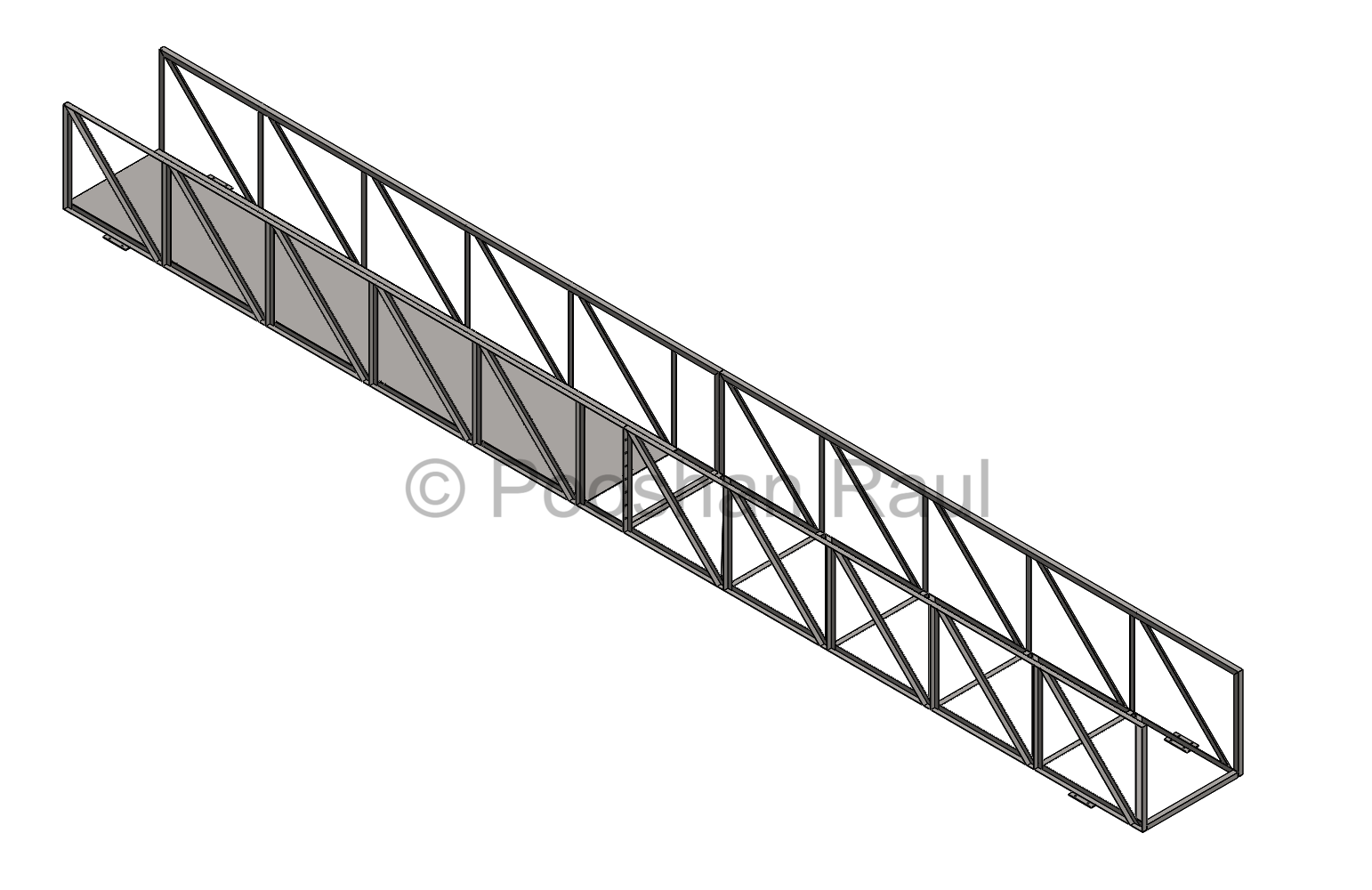
Clarifier Walkway Assembly
The bridge was designed using modular L-angle truss segments joined via bolted flanges, with added bracing for torsional resistance. SolidWorks was used for full parametric modelling, including all interfaces for drive systems and structural alignment.
- Constructed with 50×50×5 mm L-angle trusses with trim-extended joints
- Split into 2 transportable segments for ease of on-site assembly
- Gearbox, scraper, and pipe interfaces modeled to match mechanical layout
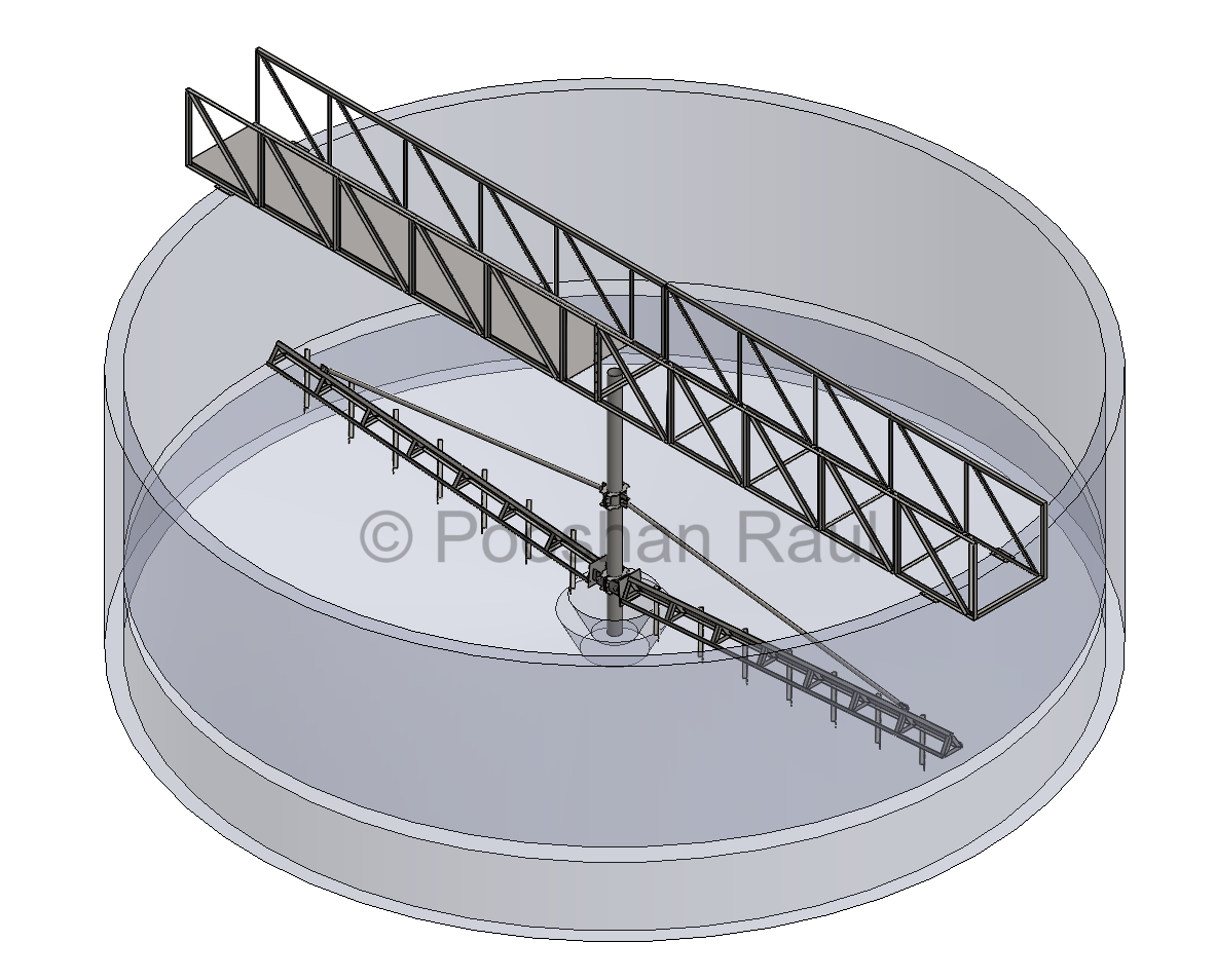
Integration with Civil Infrastructure
The truss was geometrically constrained within a cylindrical RCC clarifier tank envelope. Alignment was coordinated with anchoring plates, center shaft, and scraper coupling positions.
- Anchoring aligned to top slab rim and central feedwell structure
- Verified with P&ID and GA drawings for mechanical fit
- Scraper couplings and guide brackets included in the model
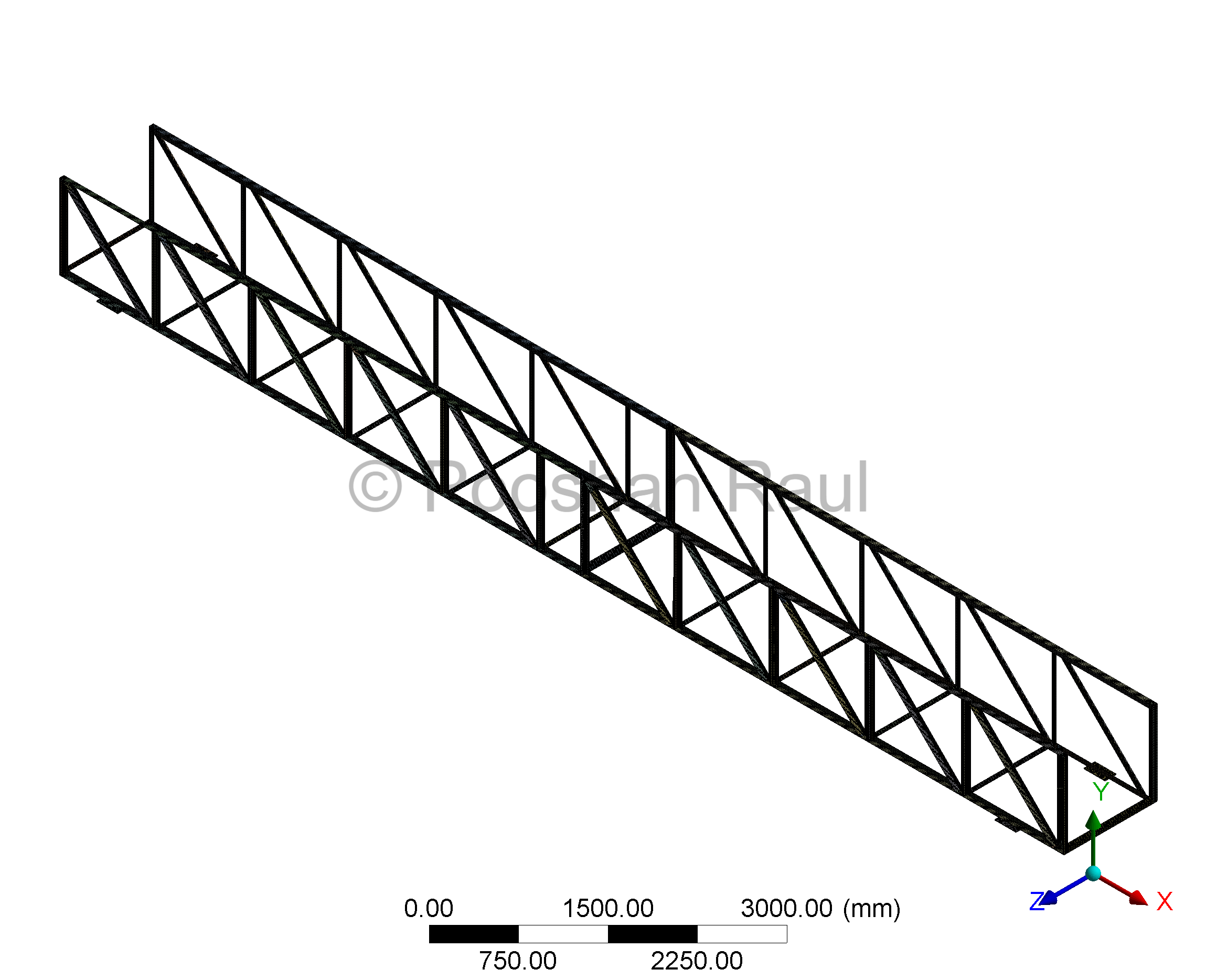
Mesh & Boundary Setup
A full 3D solid model of the walkway was meshed in ANSYS Mechanical using sweep-based hexahedral meshing. Truss members were sliced at intersections to enable conformal mesh transitions and ensure accurate stress transfer across joints. Mesh refinement was focused on bolt pads, flanges, and bracket regions to preserve accuracy under loading.
- Meshing Method: Sweep-based hex meshing with conformal slicing
- Element Type: SOLID186 (20-node quadratic hexahedrals)
- Refinements: At load-bearing points, bolt zones, and gusseted corners
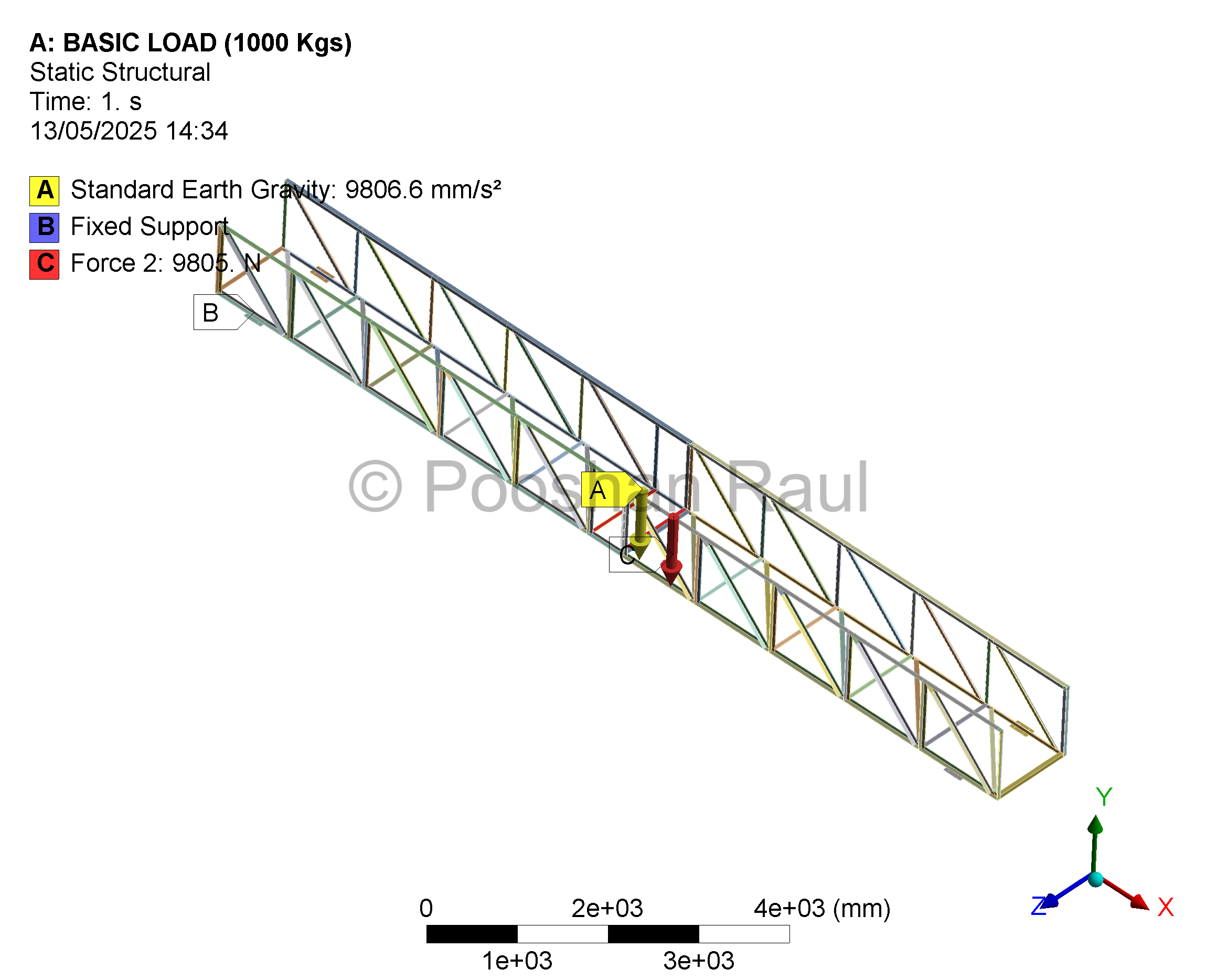
Load Case
A conservative 1000 kg load was applied at the center span to account for operational loads including the gearbox, pipe weight, and live load from maintenance. Gravity and fixed constraints were defined at anchor pads.
- 1000 kg point load at gear and scraper mount location
- Boundary Conditions: Gravity + fixed supports
- Self-weight and accessory load included in simulation
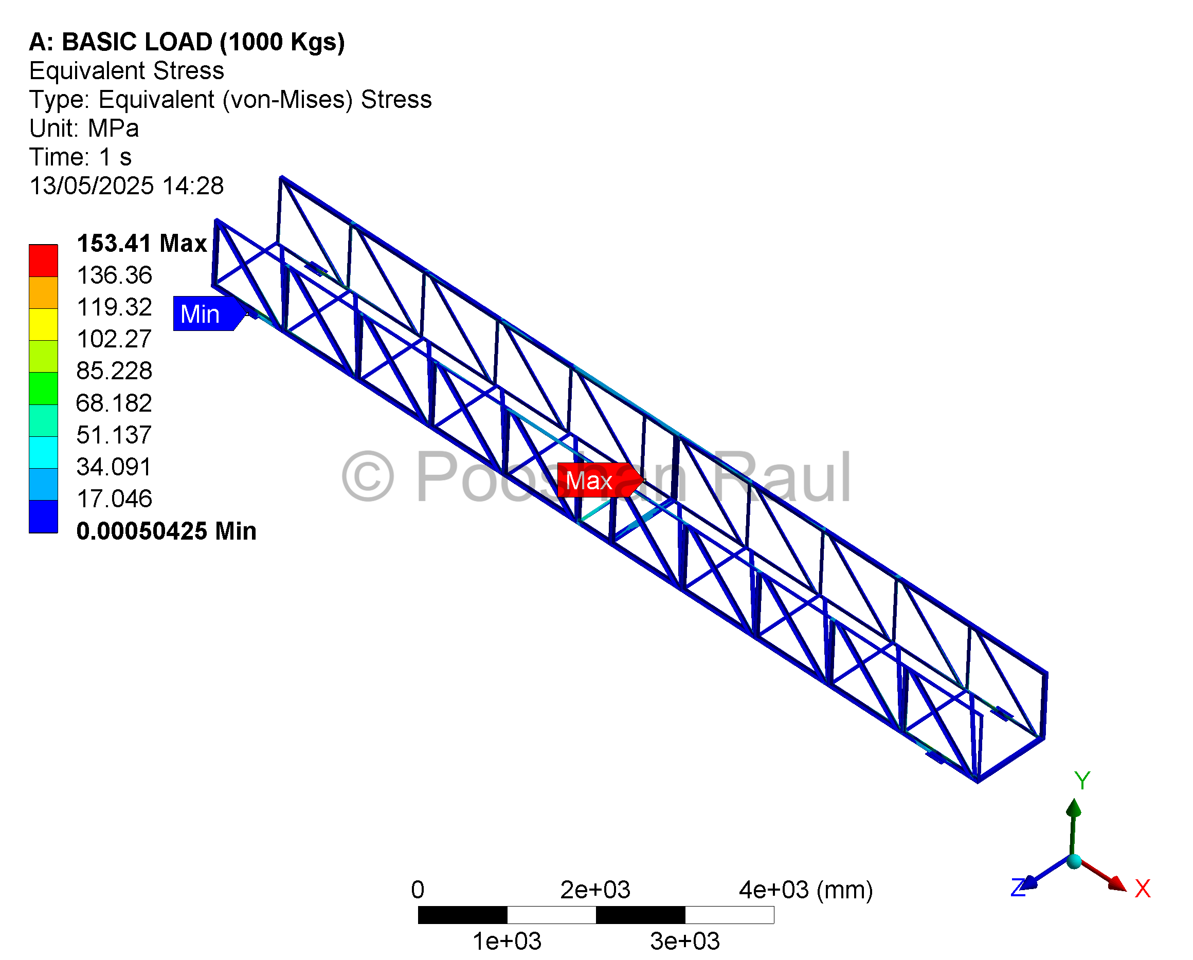
Stress Analysis
Von Mises stress contours showed peak values around bolt cutouts and joint overlaps. Stress remained safely within the material yield limit, with added bracing to distribute forces.
- Peak Von Mises stress: ~153 MPa (Yield limit: 250 MPa)
- Hotspots at bolt pads and flange joints
- Stress mitigation via filleted welds and bracing plates
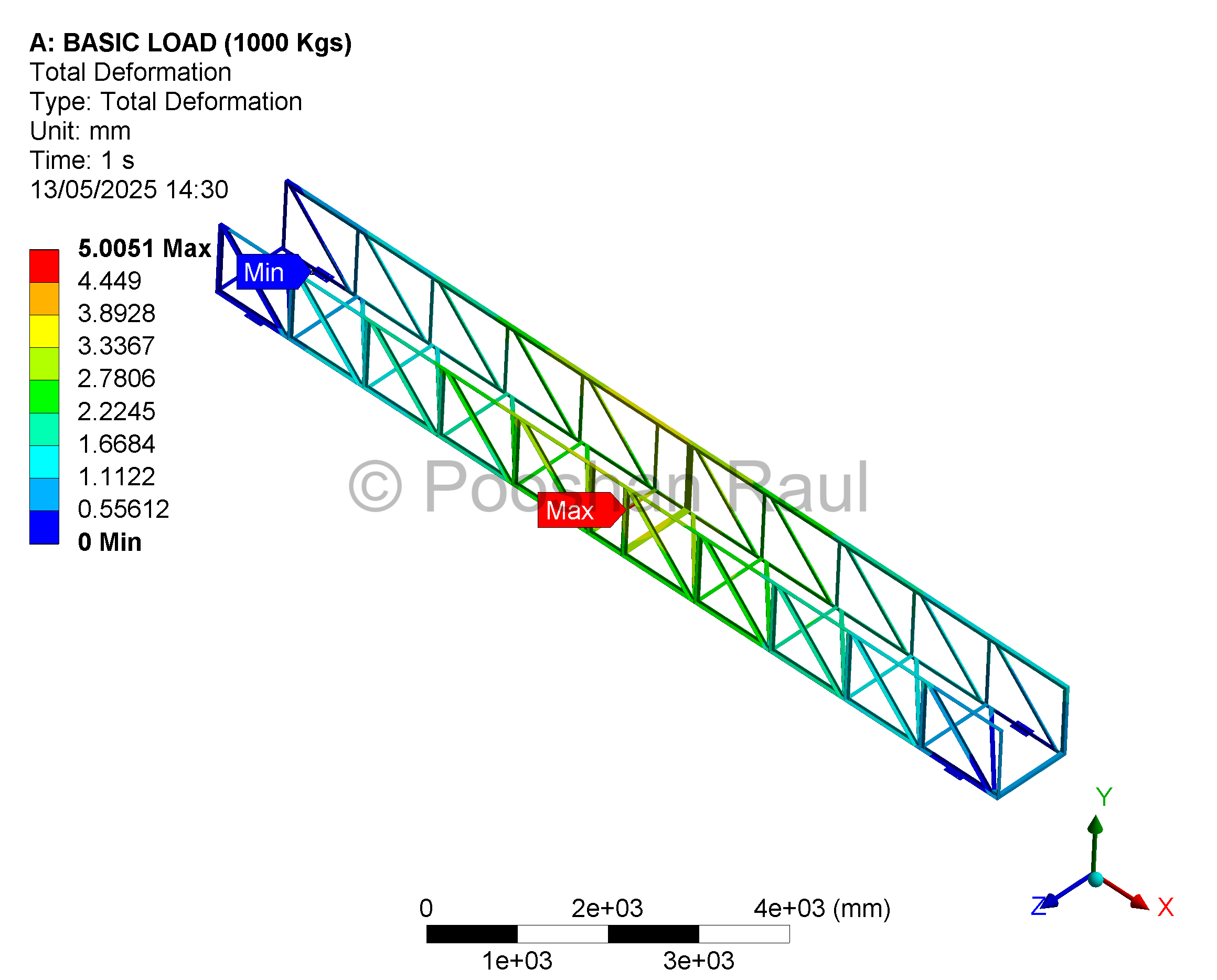
Deflection Check
The bridge deflection remained within L/250 limits for pedestrian safety. Uniform displacement was noted without mid-span torsional twisting.
- Max vertical deflection: ~5 mm (L/220)
- Passes static platform guidelines for walkable structures
- No out-of-plane torsion or lateral sway observed
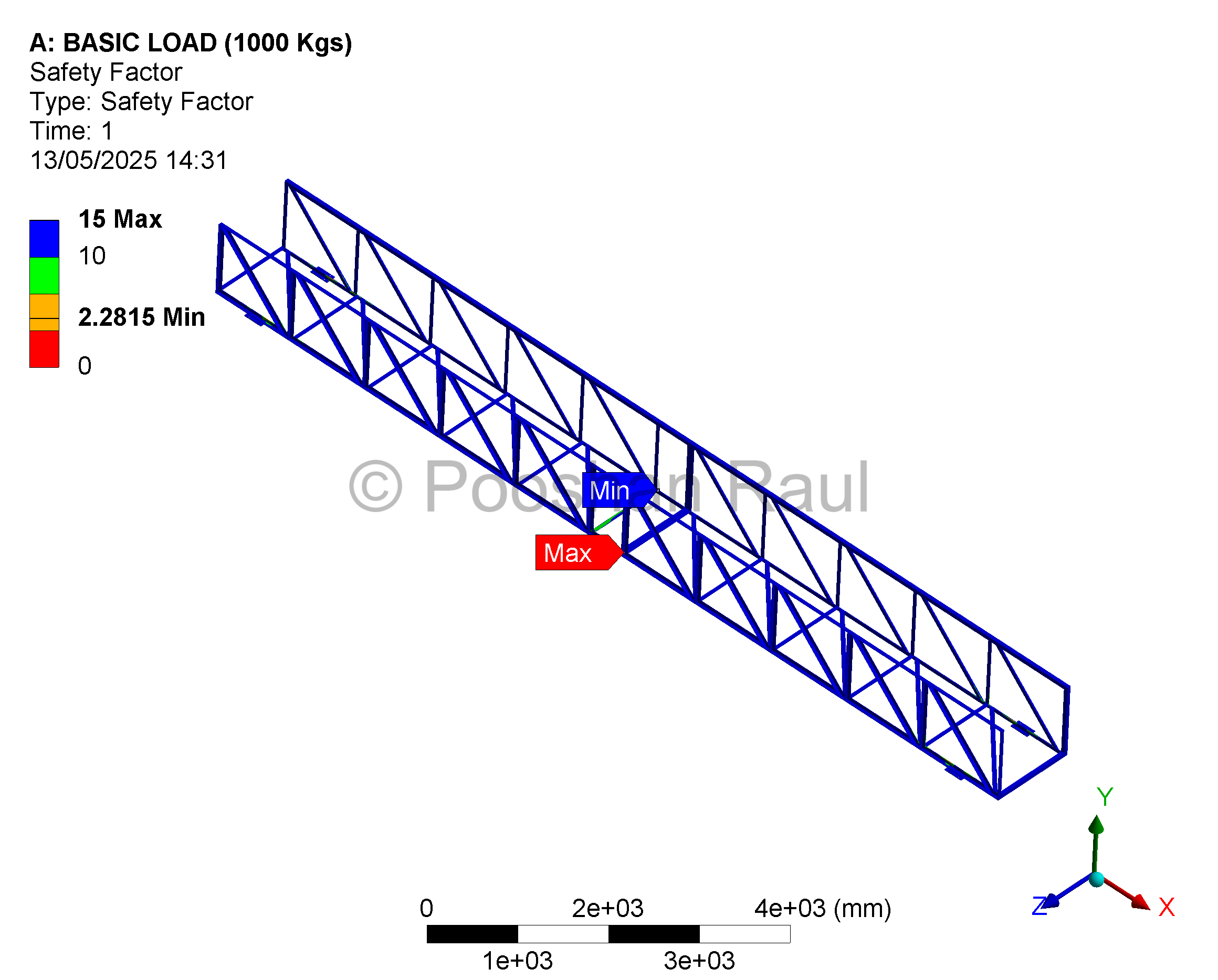
Factor of Safety
- Minimum FOS: 2.3 under peak load conditions
- Verified at truss flange junctions and anchor bolt locations
- Overdesign margin included for field variation tolerance
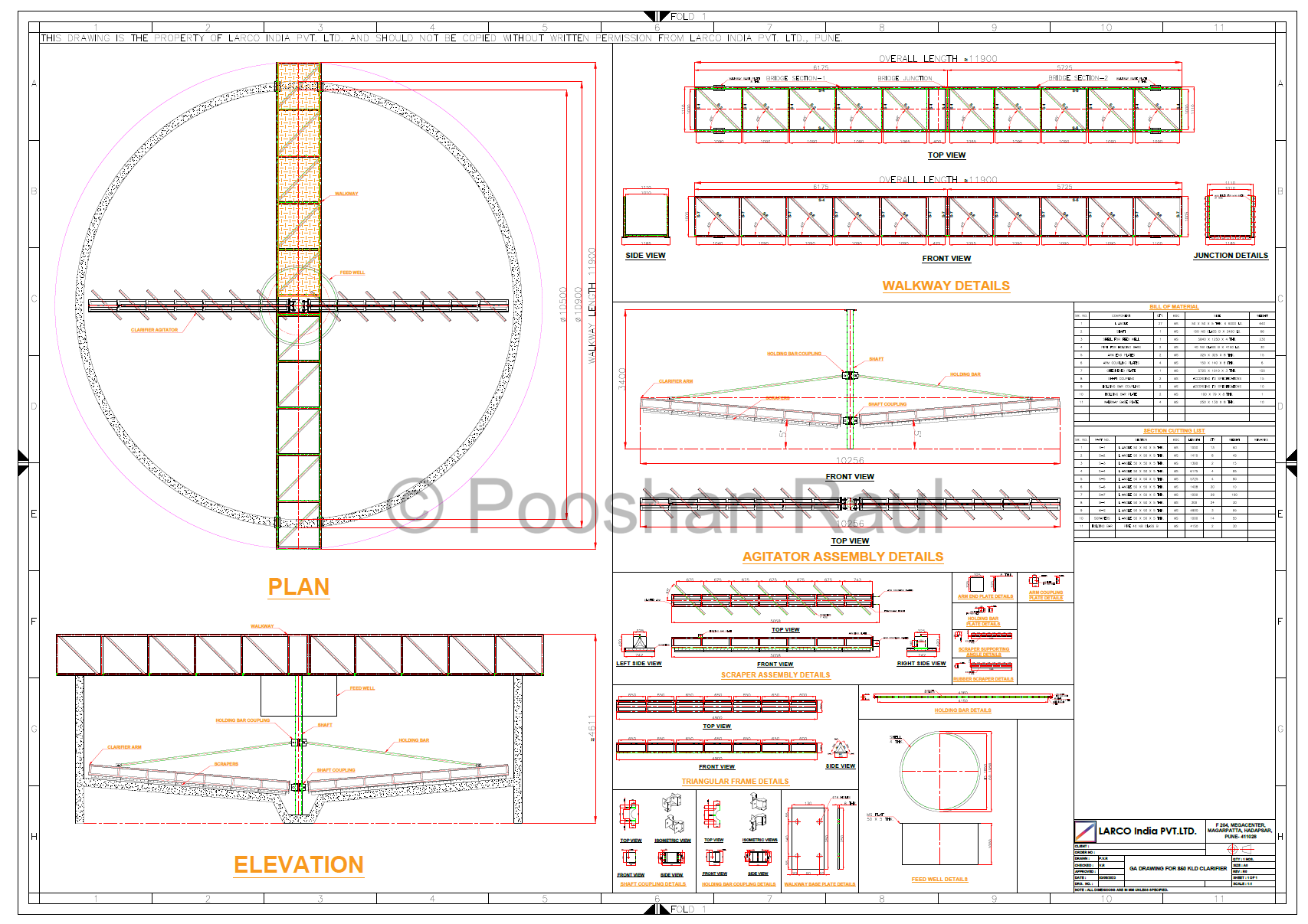
Manufacturing Drawing
The final GA drawing included all field-weld instructions, split sections, and mounting plates. BOM and weld symbols followed standard fabrication practices and were issued post-verification.
- Included weld notes, cut lengths, and BOM
- Defined fabrication split for transport constraints
- Issued post-FEA approval and client review
*Note: Drawings protected under NDA, not shown here.
Conclusion
The bridge passed all strength and deflection checks and was fabricated as per drawing without modification. On-site installation was completed successfully, and the system was commissioned with zero structural issues reported.
Project Workflow Summary
This project followed a full-cycle mechanical design process including parametric modelling, structural validation using FEA, and drawing release for fabrication. All site feedback was incorporated to ensure operational compatibility.
SolidWorks CAD → Site Coordination → ANSYS Simulation → Structural Validation → Fabrication Drawing → Final Release
Let's Connect!
Feel free to reach out to me via Email or LinkedIn.