Simulation-Driven Design of a Racing Go-Kart
This project explores the structural behaviour of a lightweight welded chassis under various loading conditions using ANSYS, with emphasis on experimental–computational correlation for high-performance applications.
Developed a simulation-led chassis design using SolidWorks and ANSYS Mechanical. Assessed front/rear impacts, torsional stiffness and modal behaviour, meeting safety factor targets and maintaining separation from the engine’s ~75 Hz operating band (first modes at 59 Hz and 117 Hz). The results prepared the frame for prototyping and enabled future experimental correlation on track.
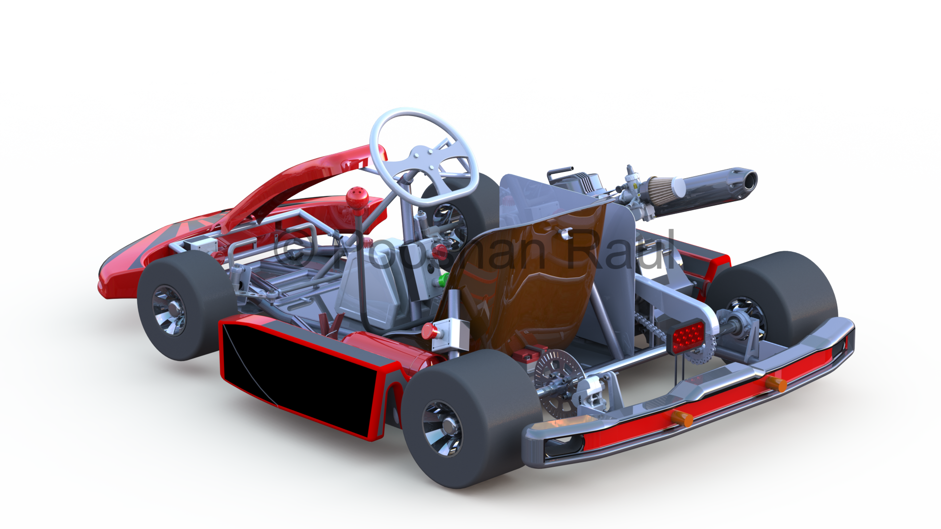
Final Assembly Render
A complete go-kart assembly was created including chassis, powertrain, steering, and safety frame. The design was developed with a focus on manufacturing feasibility and real-world race conditions.
- Engine: 124.6 cc | Max Speed: 80 km/h
- Chassis Weight: 9.2 kg
- Tools: SolidWorks, ANSYS
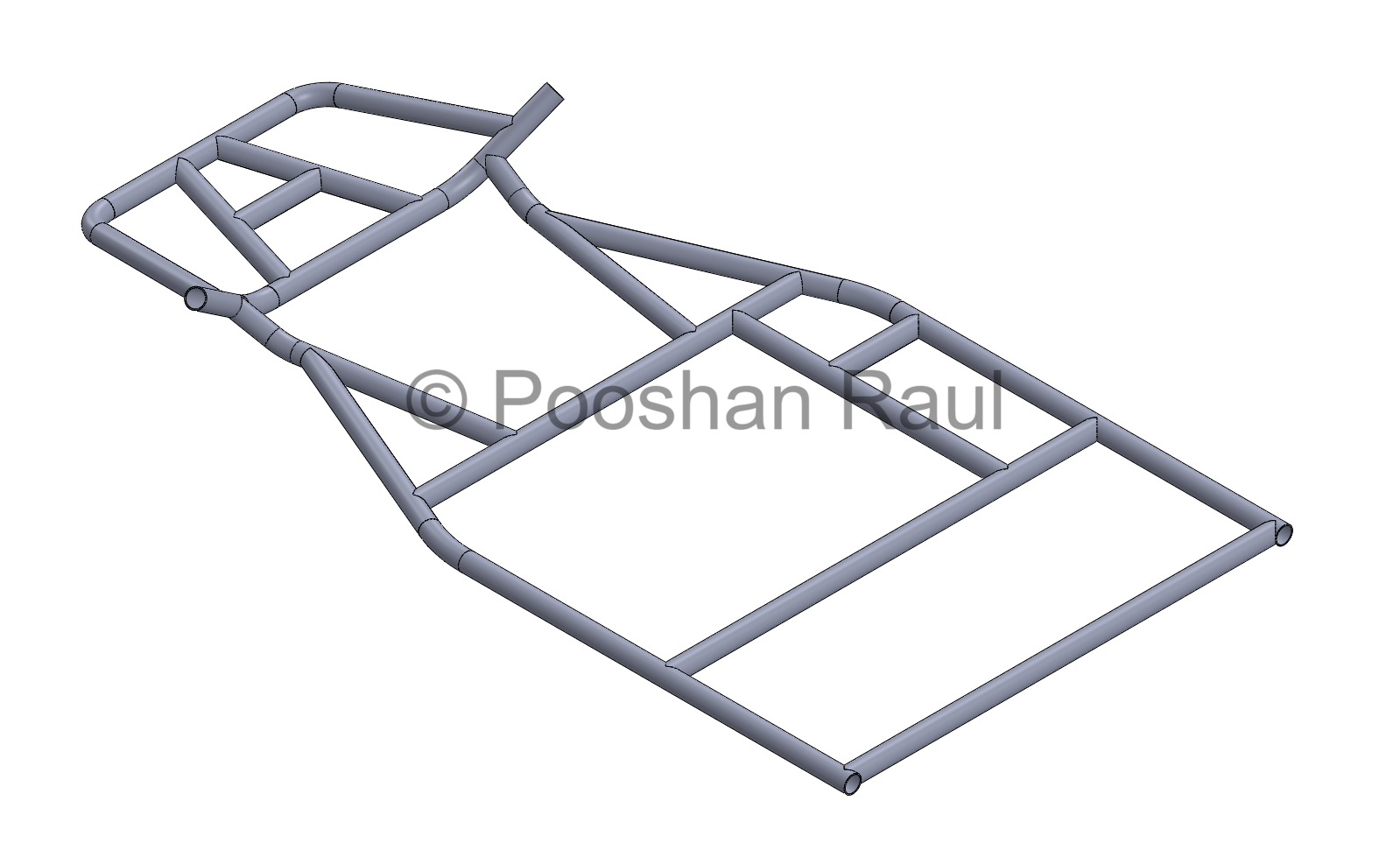
Chassis CAD Model
The go-kart chassis was constructed using tubes of identical dimensions, but with two distinct grades of AISI 4130 steel. A higher-strength variant was used at structurally critical points such as around the rear axle, engine mounts, and driver seat, where increased torsional stiffness was necessary to maintain performance integrity under race loads. In contrast, the lower-strength, more ductile variant was employed in curved members and exposed zones likely to absorb impact energy during collisions. This strategic material distribution allowed enhanced fatigue resistance and structural integrity without altering the geometric design.
- Tube Spec: 29.2 mm OD × 1.65 mm wall
- Material: Two grades of AISI 4130, stiffness and ductility-optimized
- Focus: Torsional control, fatigue life, and energy absorption through material placement
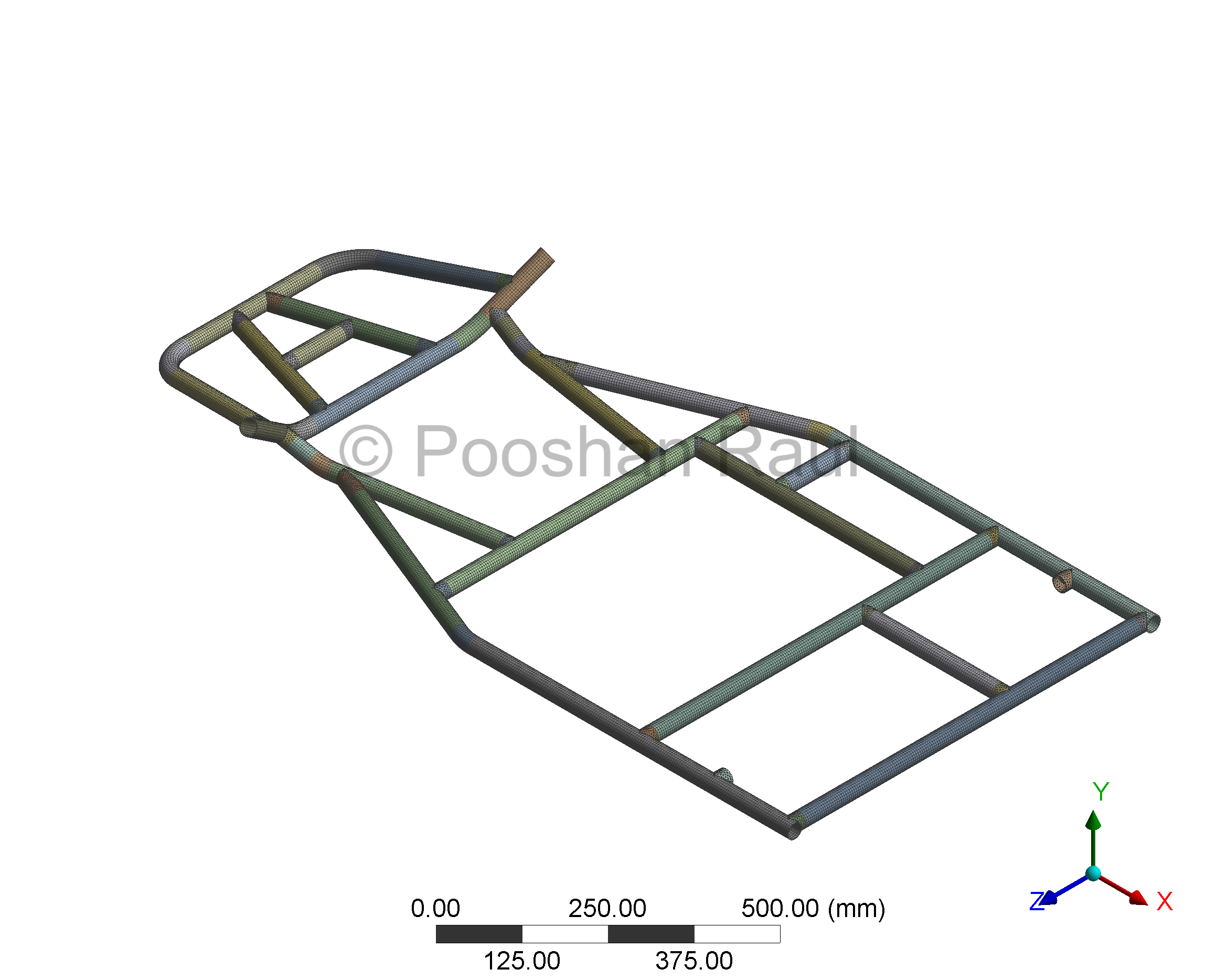
Mesh Overview
The mesh was developed using a hybrid strategy combining high-order tetrahedral (Tet10) and hexahedral (Solid186) elements. Tubular intersections and weld joints were carefully sliced and meshed with Tet10 elements to ensure geometric conformity and resolve complex junction stresses. The remaining cylindrical members were meshed using Hex elements to maximize element quality and maintain numerical stability. All interface regions were meshed conformally to ensure accurate stress transfer across members and reliable prediction of load-bearing behaviour under simulated conditions.
- Element Types: Tet10 (intersections), Solid186 Hex (tubes)
- Focus: High-quality mesh with conformal transitions for accurate structural response
- Outcome: Improved load path continuity and joint stress prediction
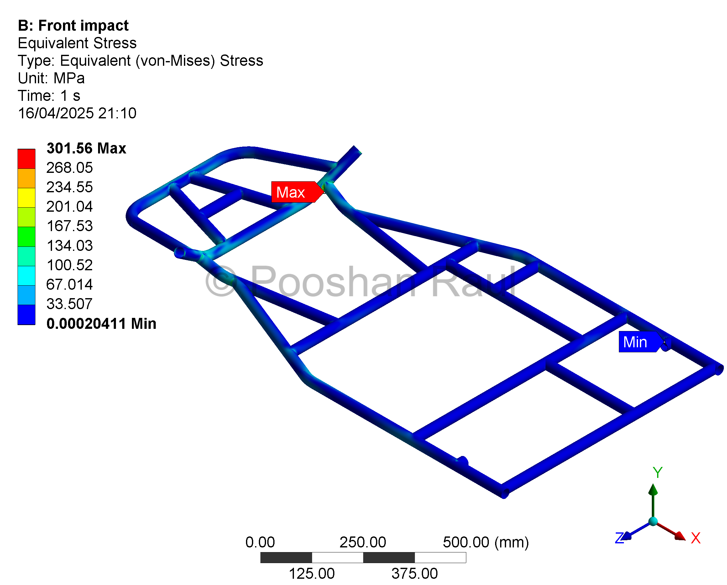
Front Impact Analysis
A deceleration force equivalent to 4G (5886 N) was applied to simulate frontal collision. The structural response was analyzed to identify deformation patterns and stress concentration regions. Post-analysis, reinforcements were suggested to improve safety margins.
- Max Stress: 301.56 MPa | FOS: 2.19
- Deformation: 0.967 mm
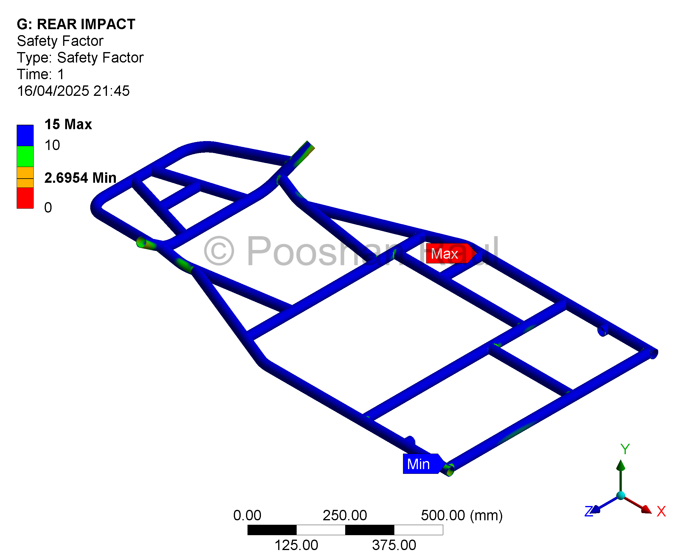
Rear Impact Analysis
A rear collision scenario was simulated under 2.5G (3678 N) loading. Frame integrity and rear-end stiffness were assessed, especially around the engine mount region, which is critical for crash energy absorption.
- Max Stress: 245.4 MPa | FOS: 2.69
- Deformation: 2.15 mm
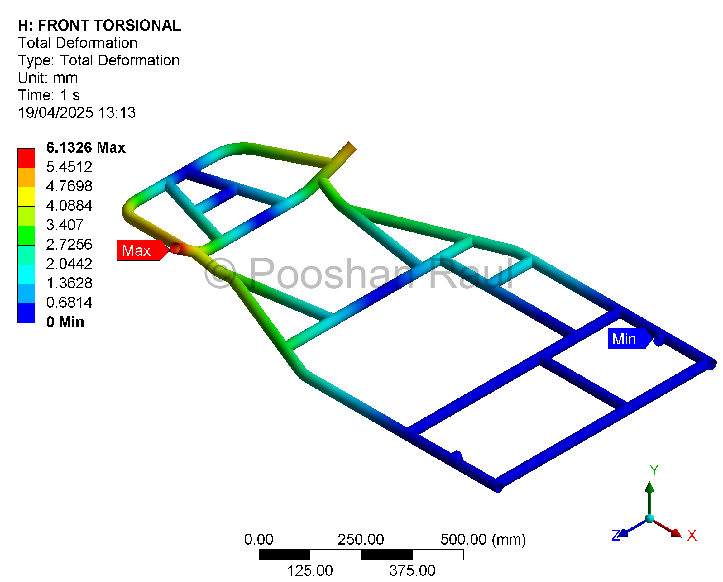
Torsional Rigidity
A torque of 367.8 Nm was applied to opposite corners of the chassis to replicate diagonal loading, representative of aggressive cornering. The simulation focused on evaluating twist resistance and identifying structural weak points.
- Deformation: 6.13 mm
- Max Stress: 613.98 MPa
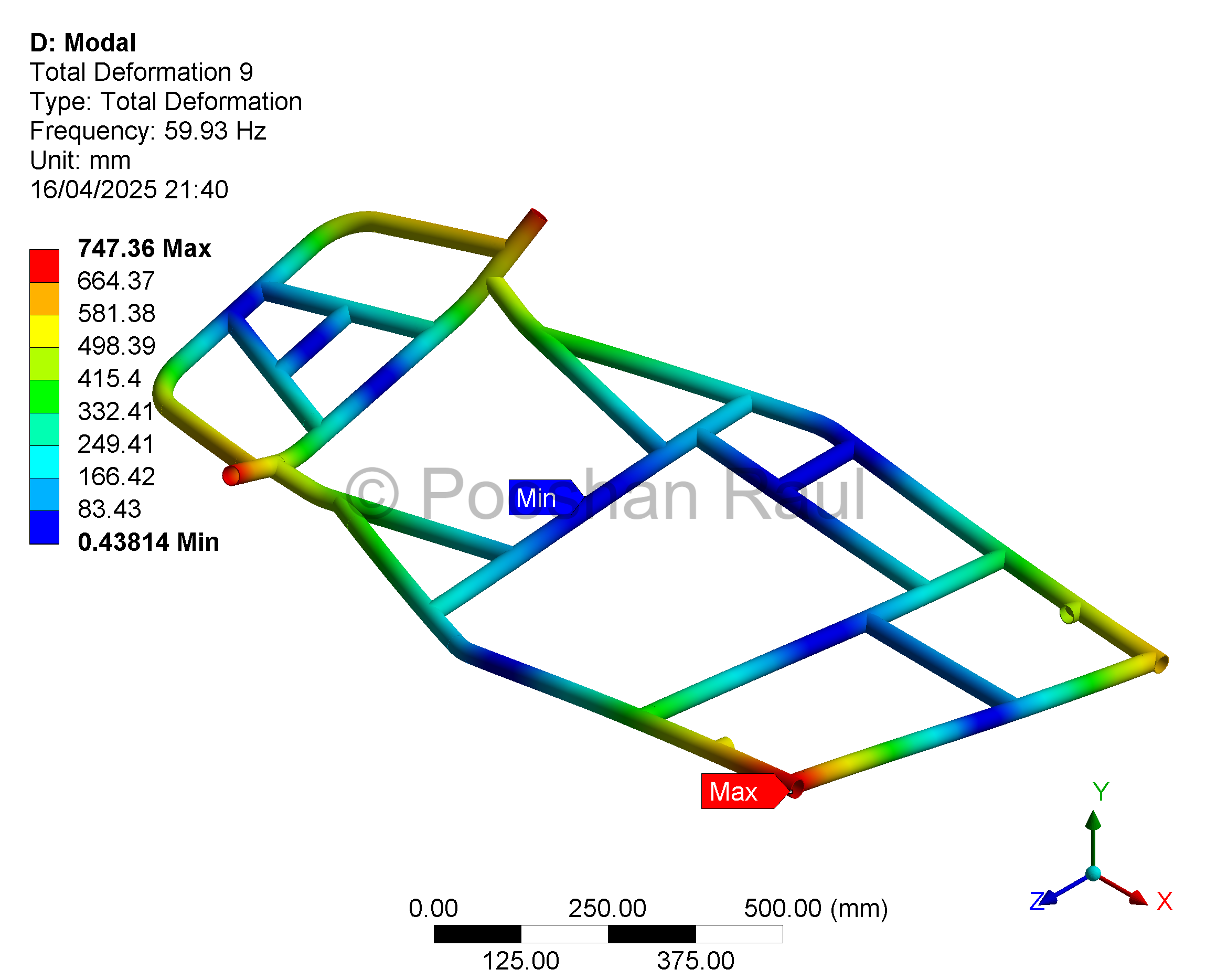
Modal Frequency Analysis
Modal analysis was conducted to identify potential resonant frequencies and prevent catastrophic failure due to vibrational excitation. Particular attention was paid to the frequencies near the engine’s operating range (~75 Hz). The first two mode shapes appeared at 59 Hz and 117 Hz, providing sufficient separation from the engine excitation frequency based on a ±10% resonance safety window. This ensured minimal risk of structural amplification. To further mitigate vibrational coupling, engine mounts were fitted with dampers to suppress dynamic responses in this critical frequency band.
- Target Check: Avoid resonance within ±10% of 75 Hz
- Primary Modes: 59 Hz (torsional), 117 Hz (lateral flexure)
- Countermeasures: Dampers installed on engine mount points
Detailed Analysis – Front Impact
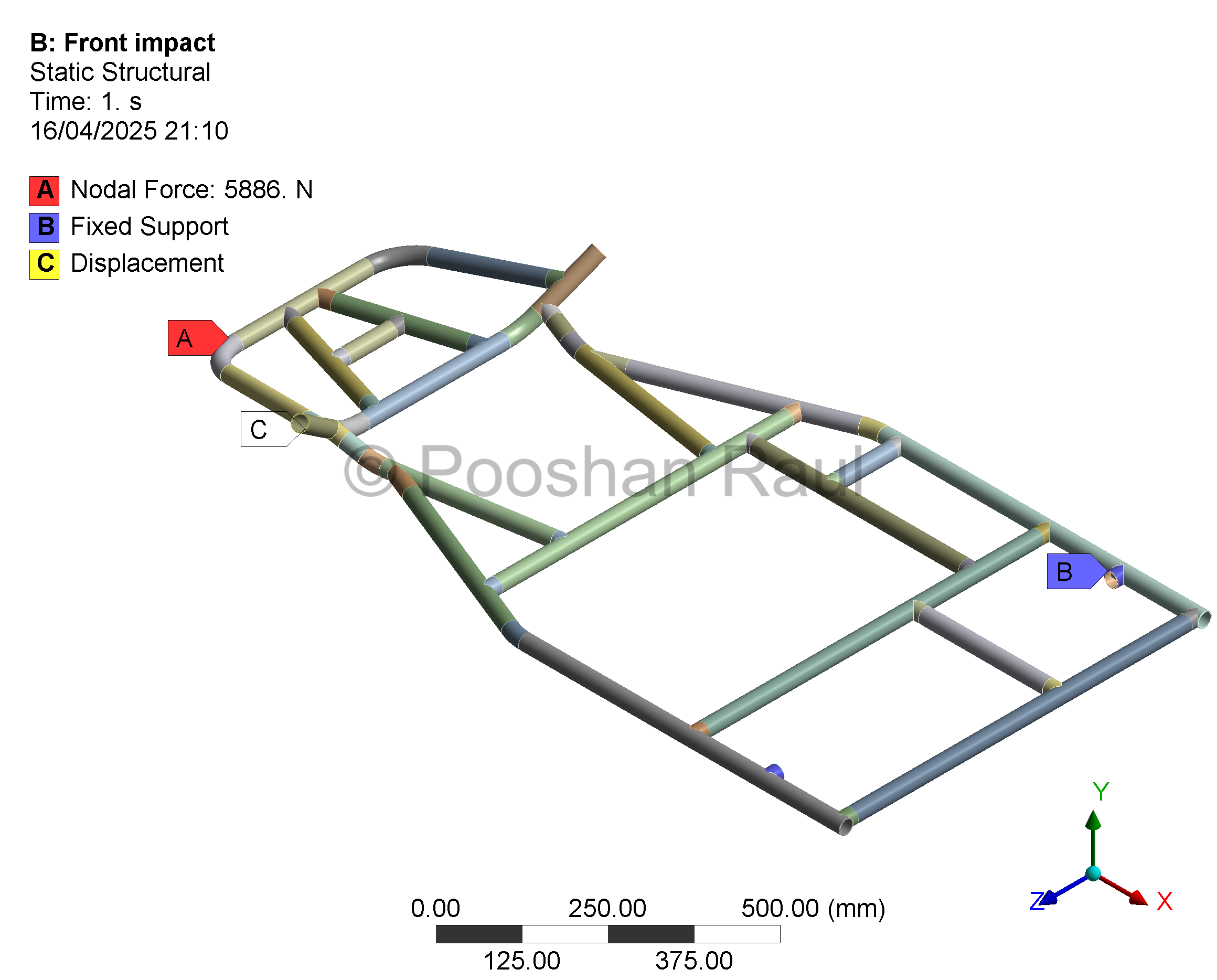
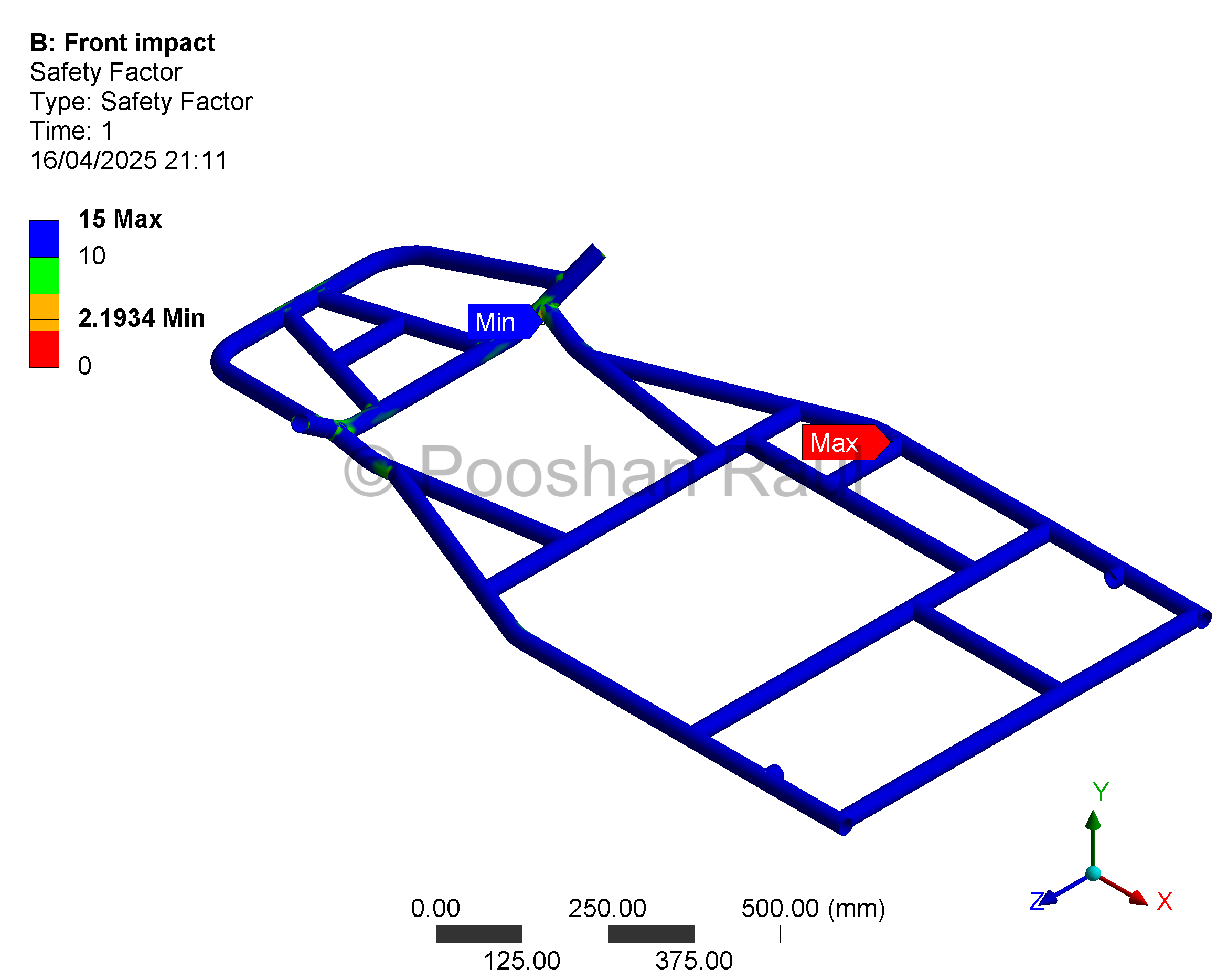
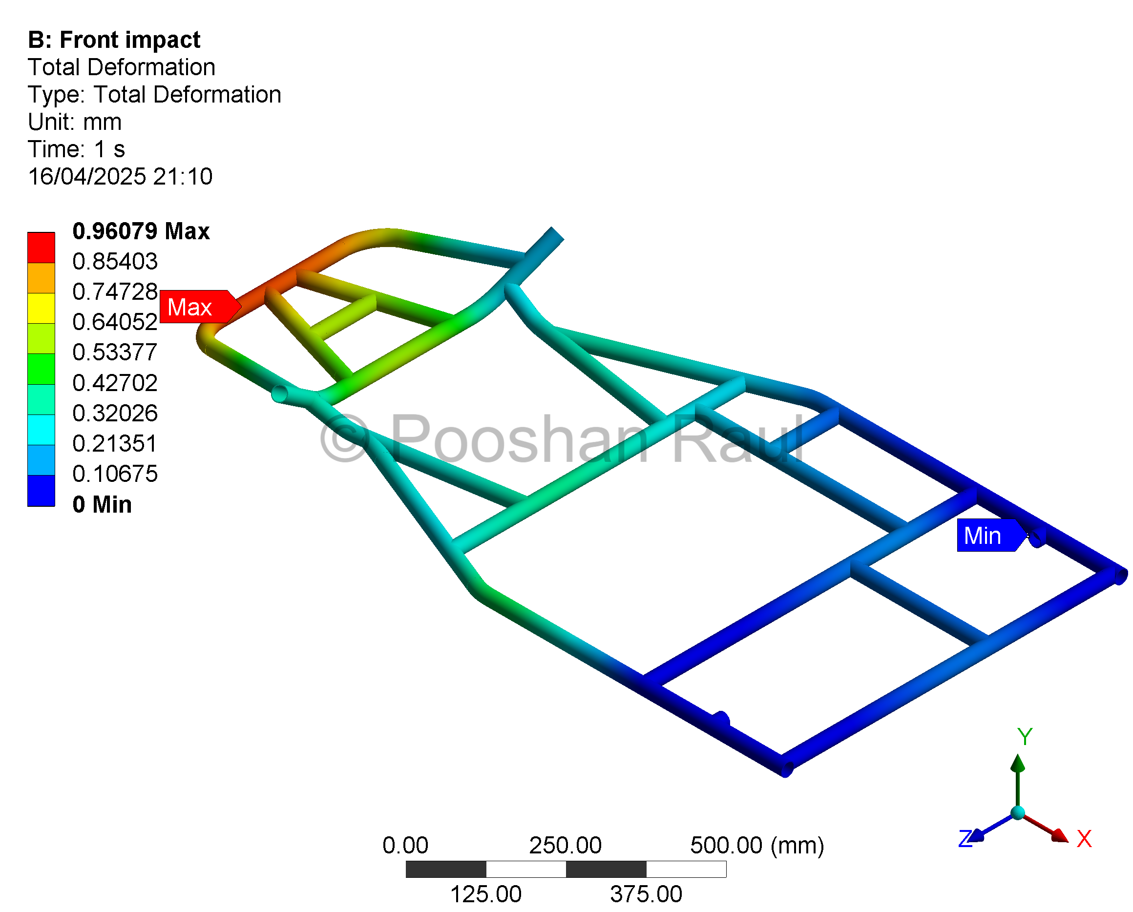
Full simulation results of the front zone under 4G impact, showing load path, deformation zones, and safety factor distribution.
Detailed Analysis – Rear Impact
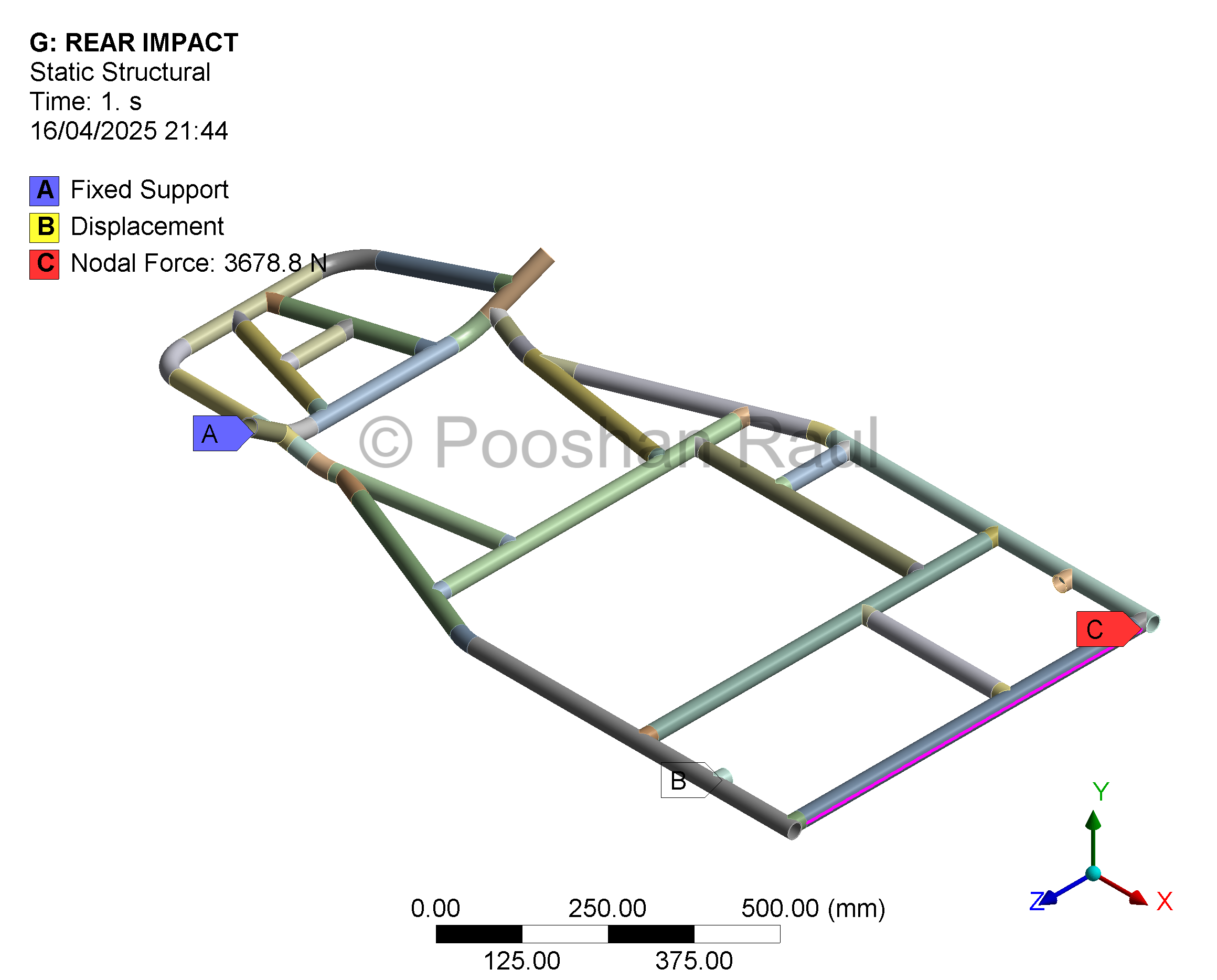
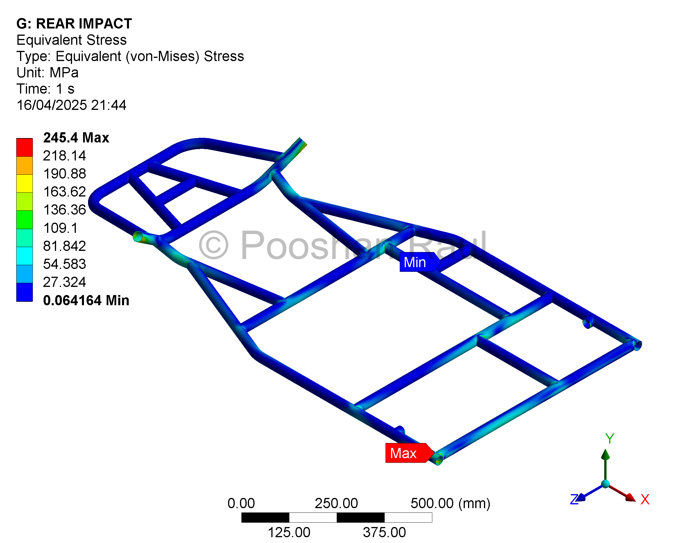
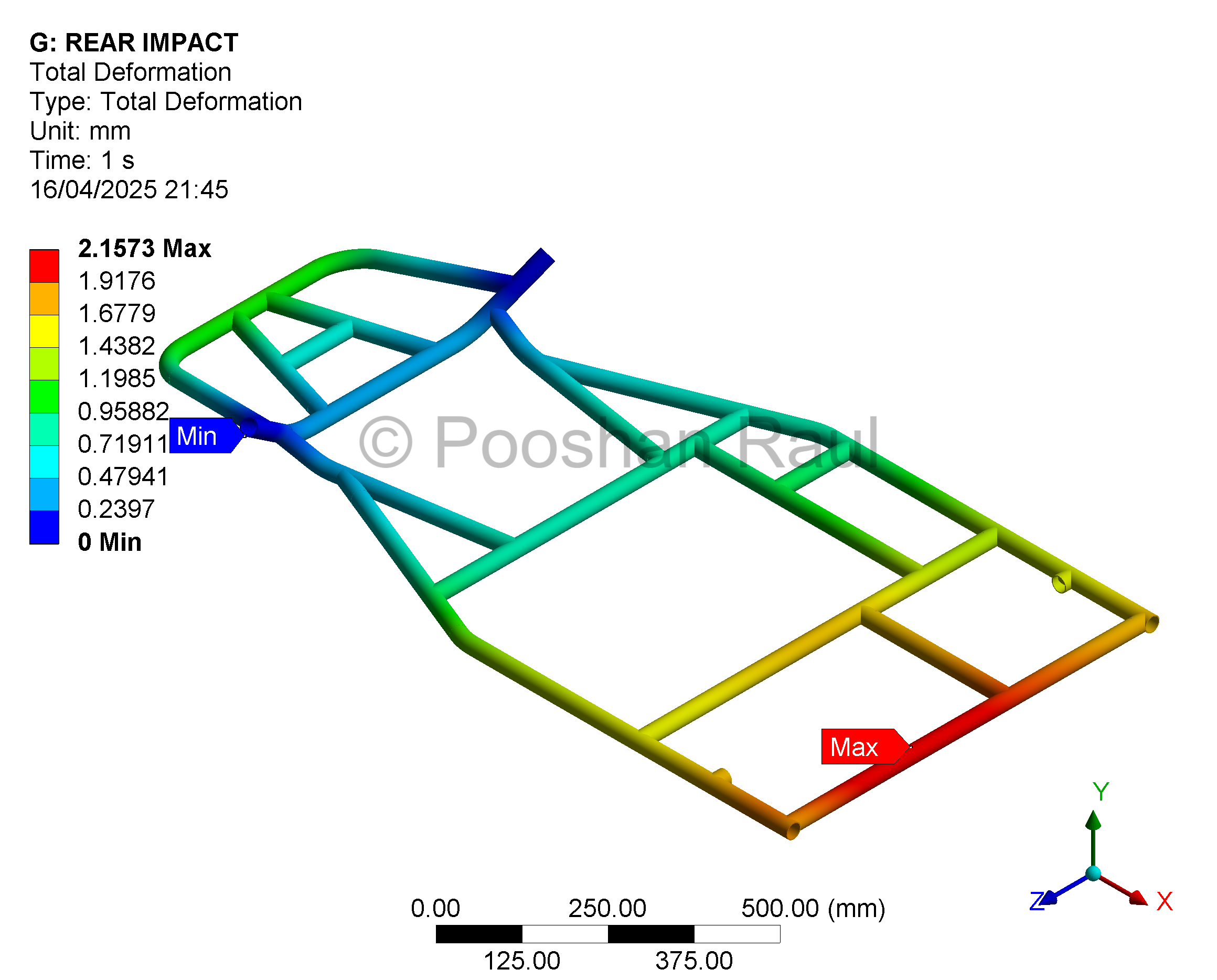
Rear impact loading focused on engine protection and rear rail behaviour. Stress and deformation maps validated structural safety.
Detailed Analysis – Torsional Rigidity
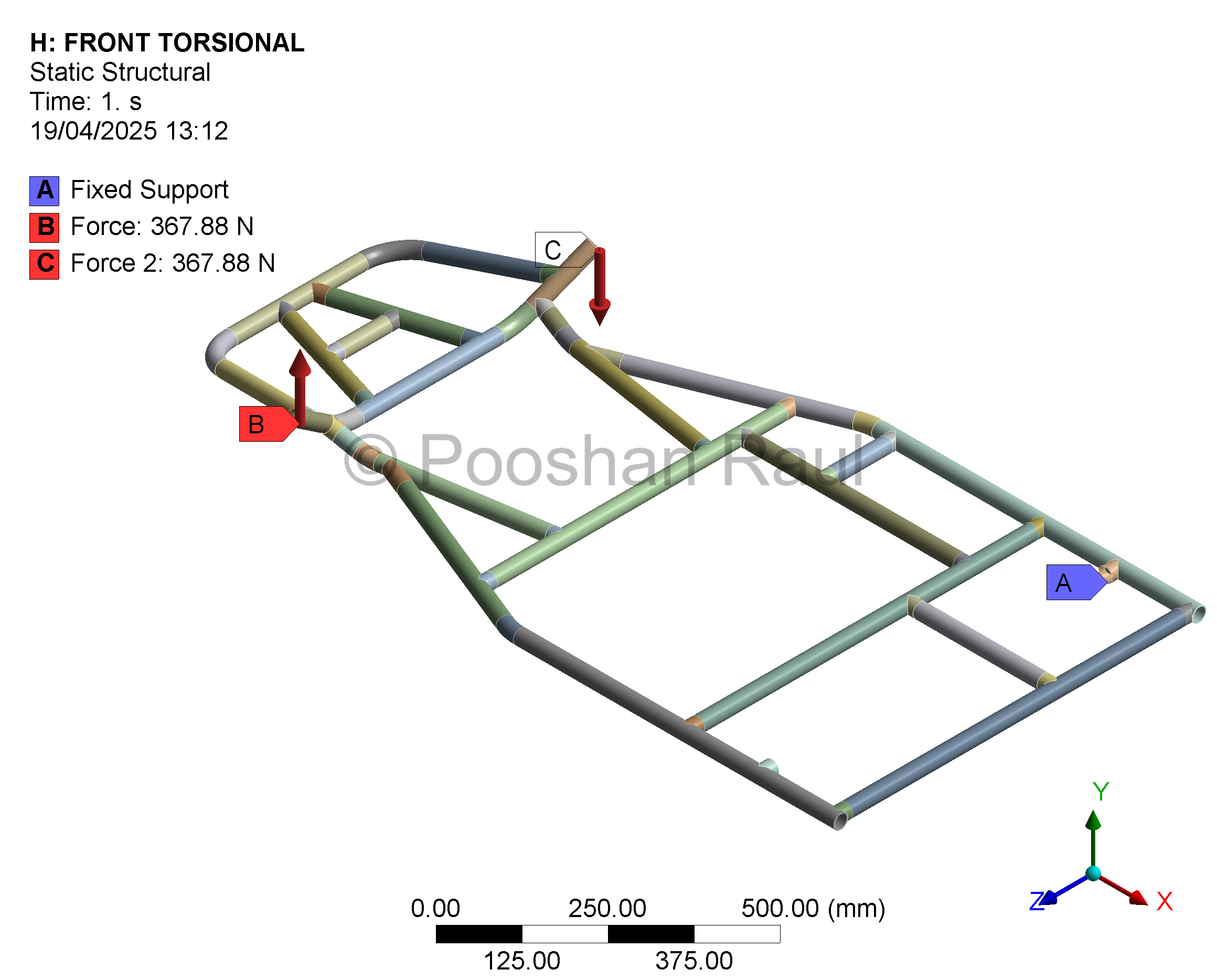
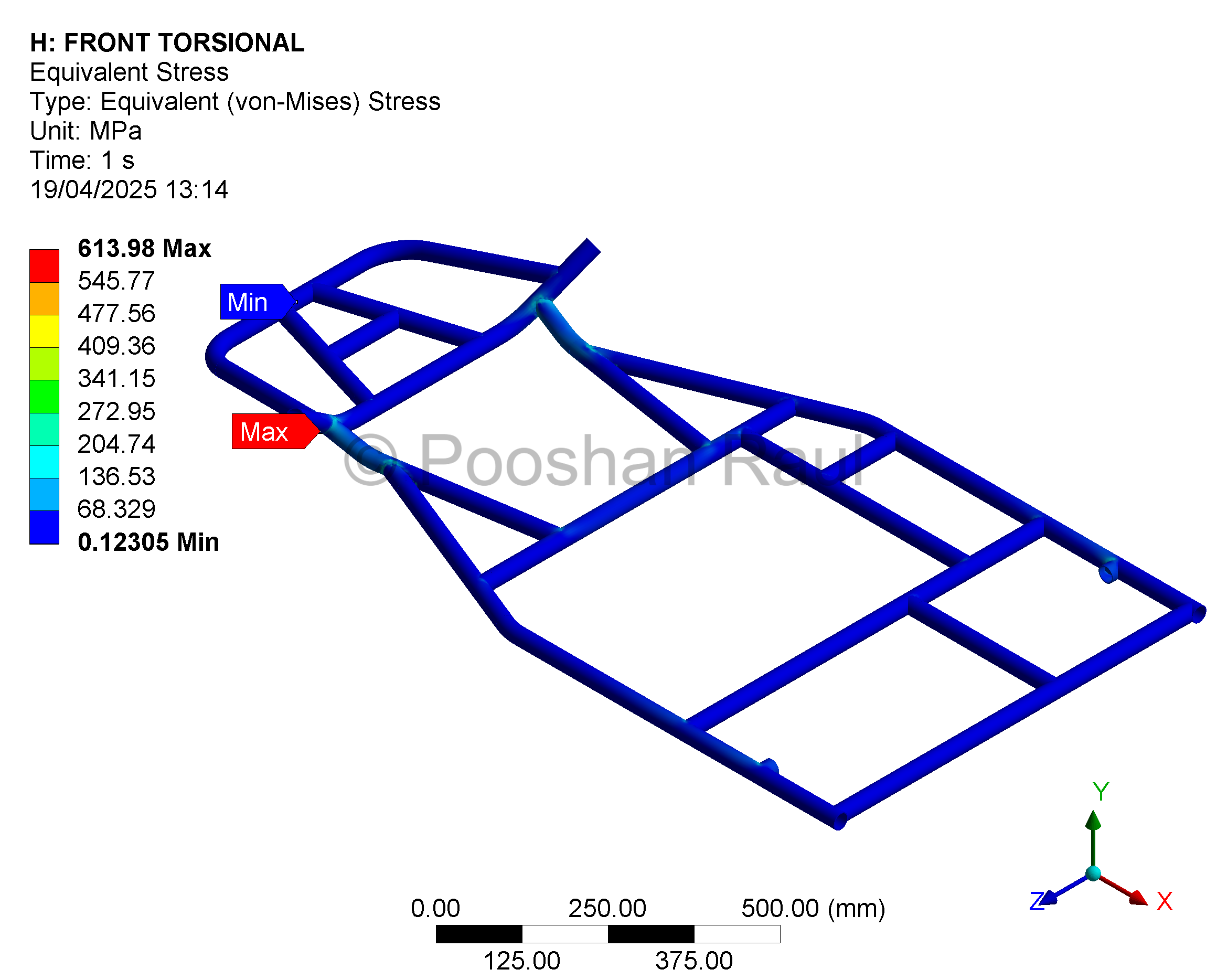
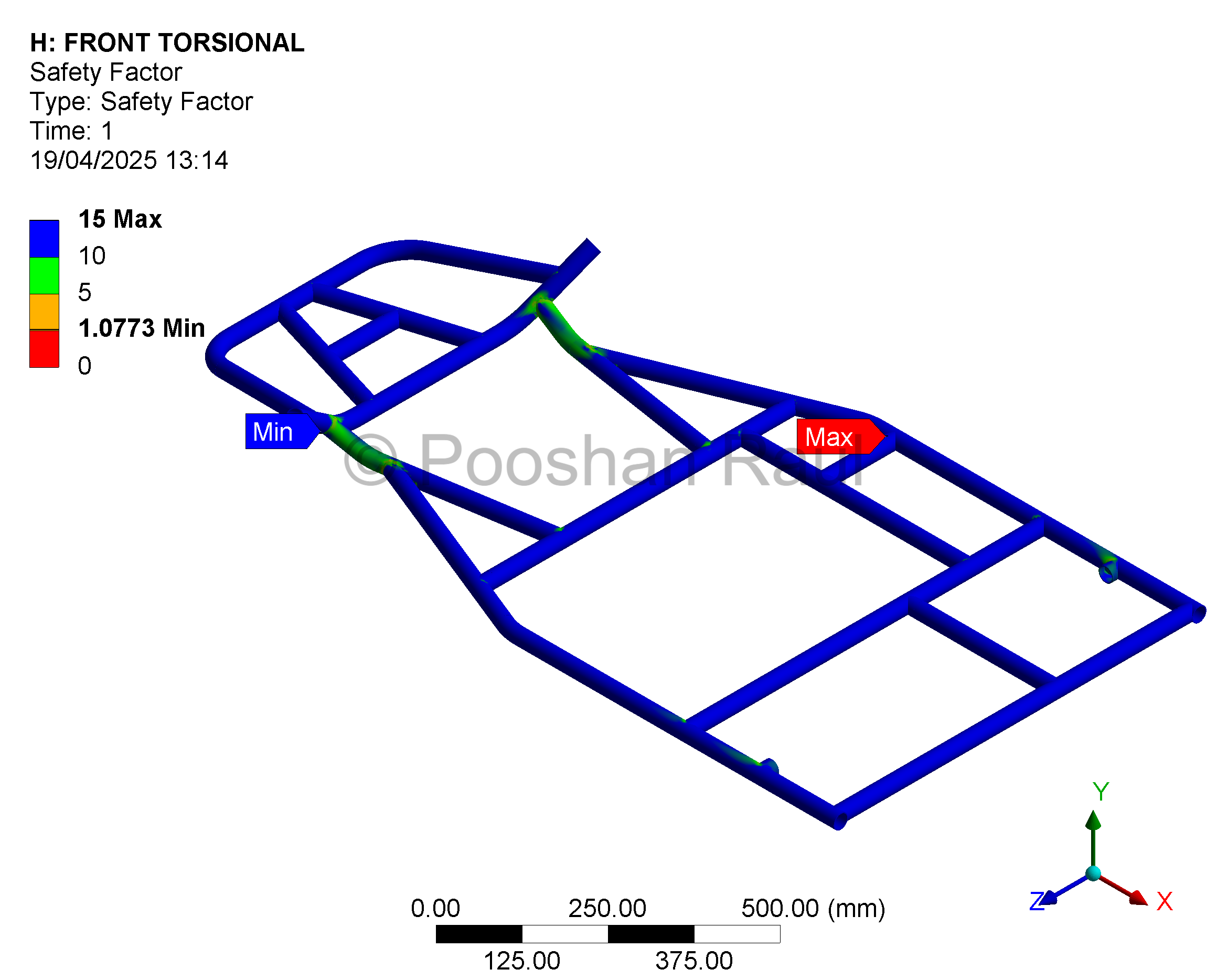
Results from diagonal torque test confirming twist control and strength at steering and mid-frame cross tubes.
Detailed Analysis – Modal Frequencies
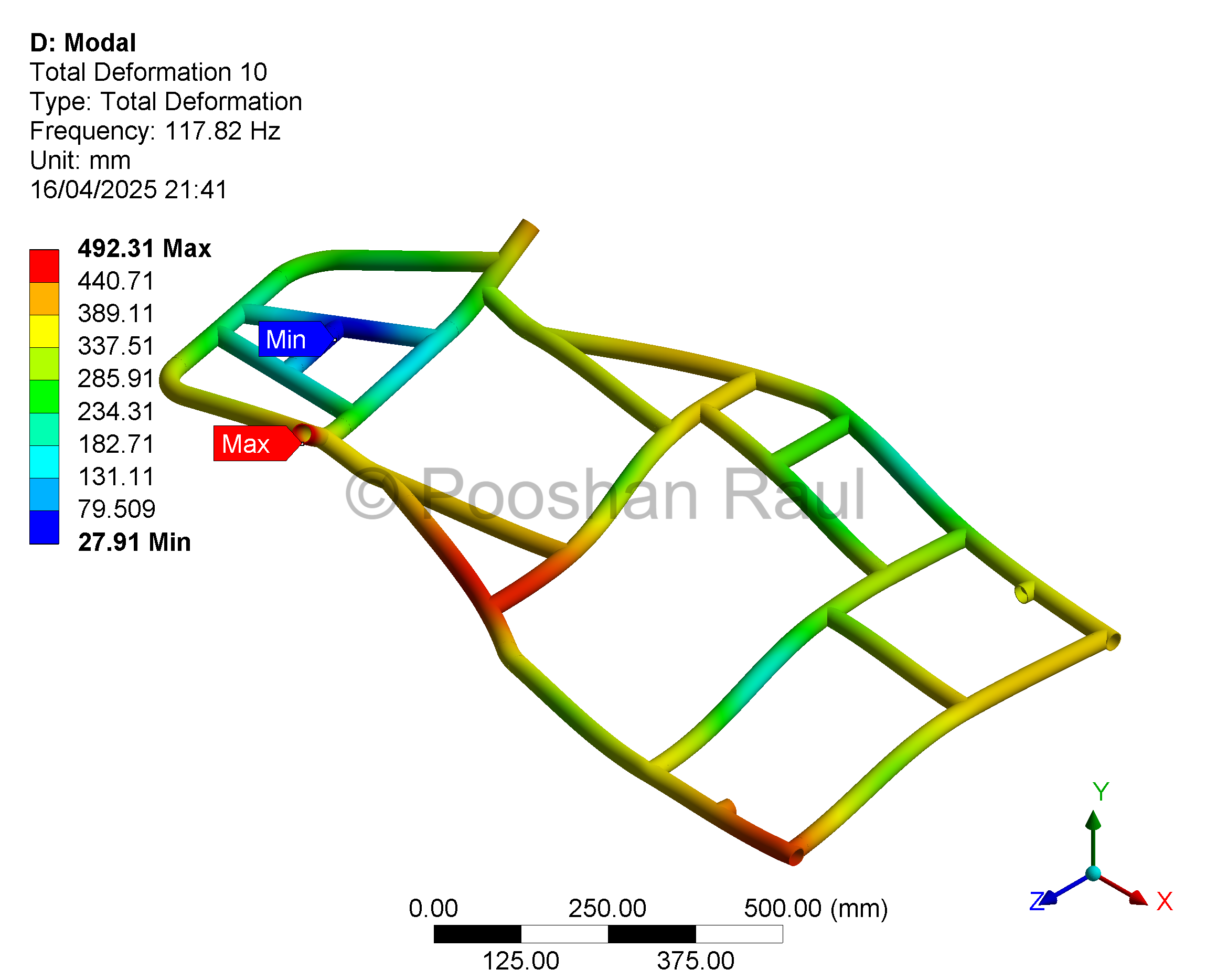
Mode shapes at key natural frequencies, confirming no vibration interference during engine or track use.
Chassis Validation Summary
| Test Scenario | Max Stress (MPa) | Max Deformation (mm) | Factor of Safety |
|---|---|---|---|
| Front Impact | 301.56 | 0.967 | 2.19 |
| Rear Impact | 245.40 | 2.157 | 2.69 |
| Side Impact (Driver) | 277.37 | 1.026 | 2.38 |
| Rear Torsion | 292.50 | 10.60 | 2.28 |
| Front Torsion | 613.98 | 6.13 | 1.08 |
Weight Distribution: 60% rear / 40% front, optimized for dynamic weight transfer.
Under braking, ~10% shifts forward improving stability. Under acceleration, rear bias improves traction.
Validation Summary: Structural response across loading scenarios demonstrated compliance with safety and stiffness targets, with stress, deformation and FOS evaluated to confirm chassis readiness for dynamic testing and real-world track conditions.
Project Summary & Engineering Workflow
This study presents a finite element–validated design for a go-kart chassis, focusing on real-world loading cases such as impacts, torsion, and resonance. The iterative simulation process ensured all safety factors were above the minimum threshold. The design is ready for physical prototyping and experimental testing.
Concept Sketch → CAD modelling in SolidWorks → Material Selection → Mesh optimisation → Setup in ANSYS Mechanical → Impact & Modal Simulations → Design Iteration & Validation
The validated frame design met all safety and performance targets, with clear documentation of stress zones and structural limits under race-like conditions.
Project Information
- Project Date: 2023
- Software: SolidWorks, ANSYS
- Category: Structural Simulation & Vehicle Design
- Focus Areas: CAD, Crash Testing, Modal, Torsion, Fabrication-Ready modelling