3D Piping & Equipment Layout for a Solvent Recovery Plant
Designed using SolidWorks, this project illustrates equipment placement, piping routes, and mechanical integration for an industrial solvent recovery process.
This project involves the detailed 3D modeling of a solvent recovery plant layout using GA drawings and P&ID inputs. The design emphasized equipment modularity, serviceability, and manufacturability. Piping systems were routed for process logic and elevation safety, and the final output included a BOM and simulation-ready geometry following ASME layout standards.
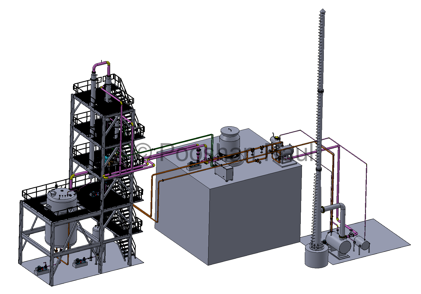
Plant Assembly Overview
The model integrates all core process equipment including the reactor, distillation tower, condensers, and receiver tanks. Spatial optimization and pipe zoning were used to minimize footprint and reduce pressure drop across long transfer lines.
- Equipment: 20 KL Reactor, 10 M Column, 30 m² & 10 m² Condensers
- Process Units: 200 L Reflux Drum, 1.5 KL Receiver
- Outcome: Parametric, fabrication-ready model with structured BOM
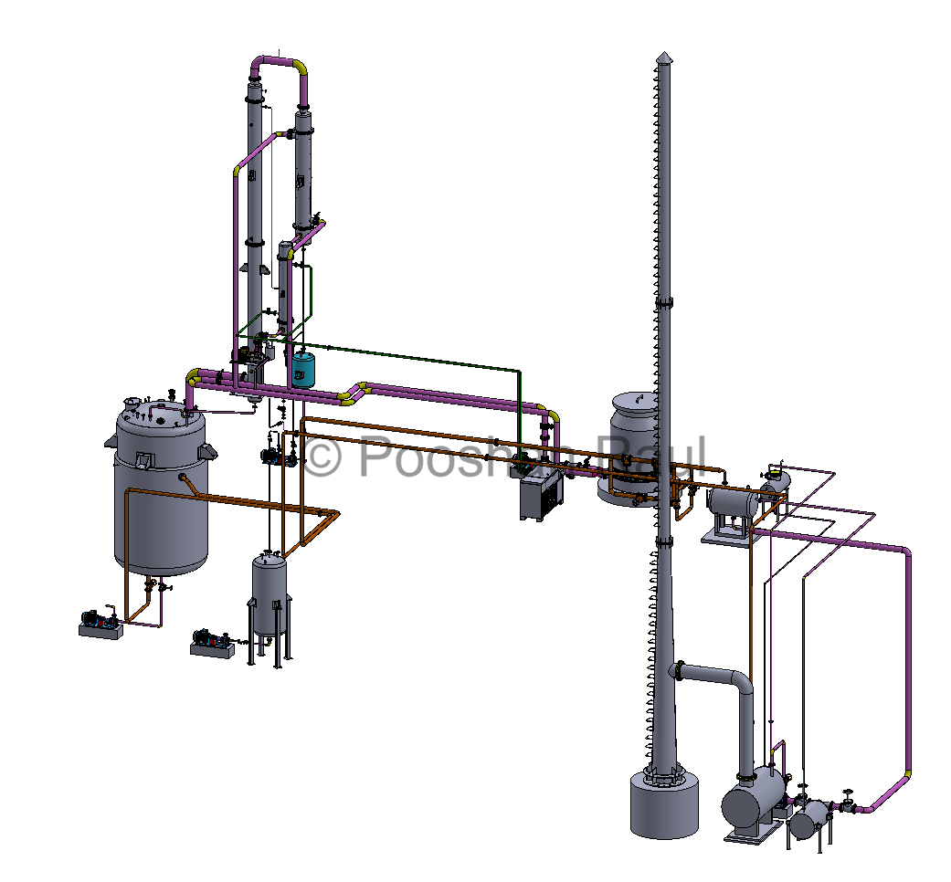
Line Routing & Detailing
Pipe routing was performed using P&ID-driven flow zoning, ensuring no elevation or access conflicts. Thermal and head losses were minimized with optimized route lengths, and piping grouped by process type (e.g. vapors, condensates, solvents). Each elevation was validated against platform GA.
- Elevation Levels: Multi-floor layout, 3000 mm elevation increments
- Validation: Cross-referenced with platforms and stair accesses
- Result: Clean separation between mechanical and process lines

Boiler and Cooling Zone Design
The cooling section included thermal fluid heaters, chillers, and auxiliary tanks. Components were placed for optimal ventilation and drainage, with OEM interface specs defining nozzle alignment and support bracket positions.
- Drainage Floor: Grating-based layout for fluid runoff
- Ventilation Zones: Included for all heat sources
- OEM Considerations: Flange clearances, lifting eye positions
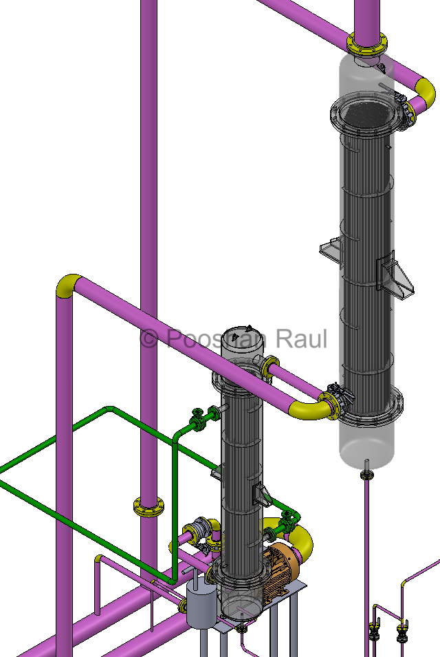
Condenser Design and Piping
Each condenser unit was designed using ASME code for mechanical design and plant operation, with fabrication elements like nozzle pads, stiffener rings, dish ends, and platform supports.
- Standard: ASME Section VIII design, layout and welding guidelines
- Details Included: Nozzle flanges, dish heads, Lifting lugs, support brackets
- Outcome: Fabrication drawing, BOM ready for costing and manufacturing
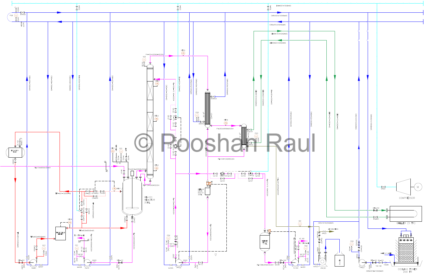
P&ID-Driven Piping Logic
P&ID interpretation drove tag-based line routing, grouping, and valve placement. Final output included a tagged and uniquely numbered BOM. NPT-threaded fittings were limited to instrumentation, with all process lines flanged to ASME B16.5 Class 150.
- Valves Used: Ball, Gate, Globe, NRVs, Control valves
- Piping Zones: Process, pneumatic, utility, instrumentation
- Output: BOM with unique line identifiers and tag codes
*Note: P&ID files are protected under NDA and not shown here.
Project Summary & Layout Workflow
This project demonstrates the complete design workflow of a modular solvent recovery plant based on engineering documentation (GA + P&ID). All flanged equipment interfaces followed ASME B16.5 standards. Final output included a clash-free piping layout, condenser fabrication packages, and a structured tagged BOM.
All flanged connections were modeled using ASME B16.5 Class 150 specifications, ensuring standardized bolt patterns, gasket clearances, and mating surfaces across equipment junctions.
GA & P&ID Interpretation → Equipment Modeling in SolidWorks → Structural Platform Creation → Piping Routing → BOM Extraction & Feasibility Check
The model layout supports structural simulation, interference detection, and vendor-ready fabrication documentation — enabling field installation with minimal rework.
Project Information
- Project Date: September 2021
- Software: SolidWorks
- Category: Process and Extraction
- Focus Areas: Layout Planning, BOM Optimization, P&ID Mapping, ASME-Compliant Modeling