Design and Simulation of a Pressure Vessel Using ASME BPVC Section 8 Division 2 Guidelines
Stress analysis and validation of a 500 L vessel with nozzle loads and thermal pressure, verified using ANSYS per ASME Section VIII Div. 2 through stress linearisation.
Performed ASME Section VIII Division 2 design-by-analysis on a 500 L vessel using ANSYS Mechanical. Included realistic pressure and nozzle loads, mesh refinement at stress concentration regions, and stress linearisation along critical paths. Peak membrane plus bending stresses remained below allowable limits for SA-516 Gr.70 material, confirming code compliance with margin. This demonstrates the ability to link FEA workflow with industry design codes for safe fabrication.
3D CAD Model
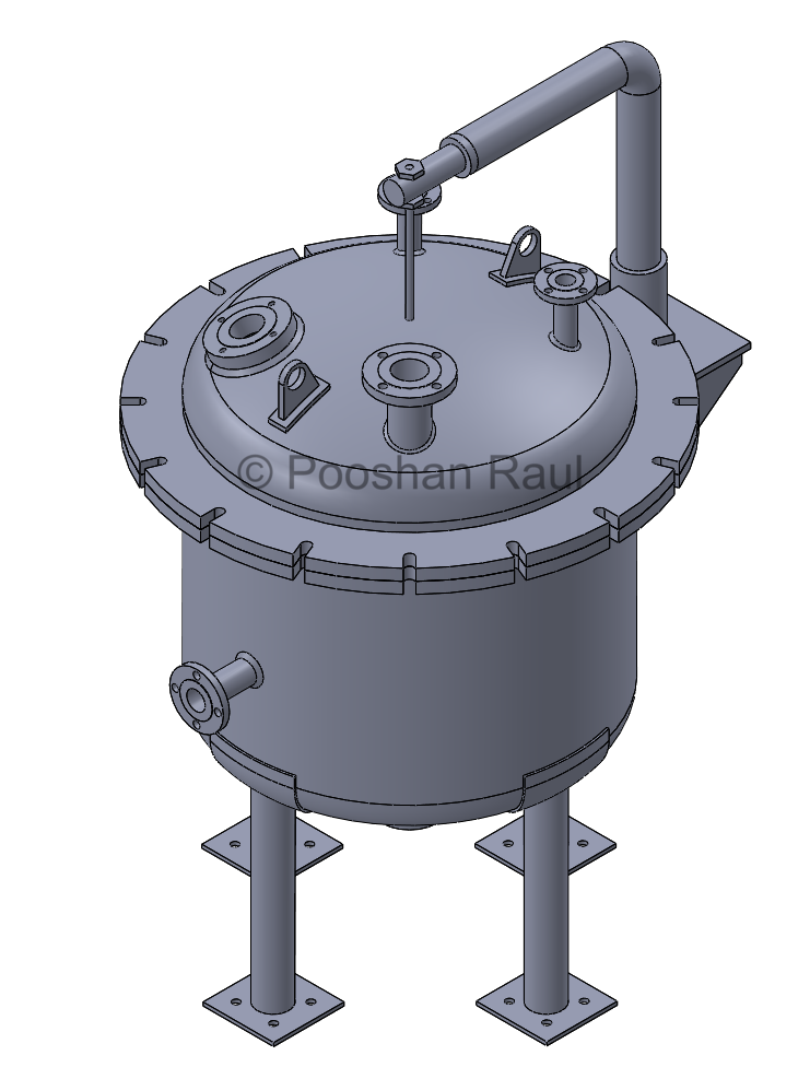
The vessel was modeled in SolidWorks with a cylindrical shell, torispherical dish ends, and six nozzle connections. Geometric simplifications such as small faces and inexact edges were excluded to ensure a mesh-friendly model for FEA.
- Volume: 500L | Thickness: 6 mm
- Nozzles: Handhole, Vent, Drain, Vacuum, Spare, View Glass
- Dish Ends: 10% Torispherical
Mesh Strategy
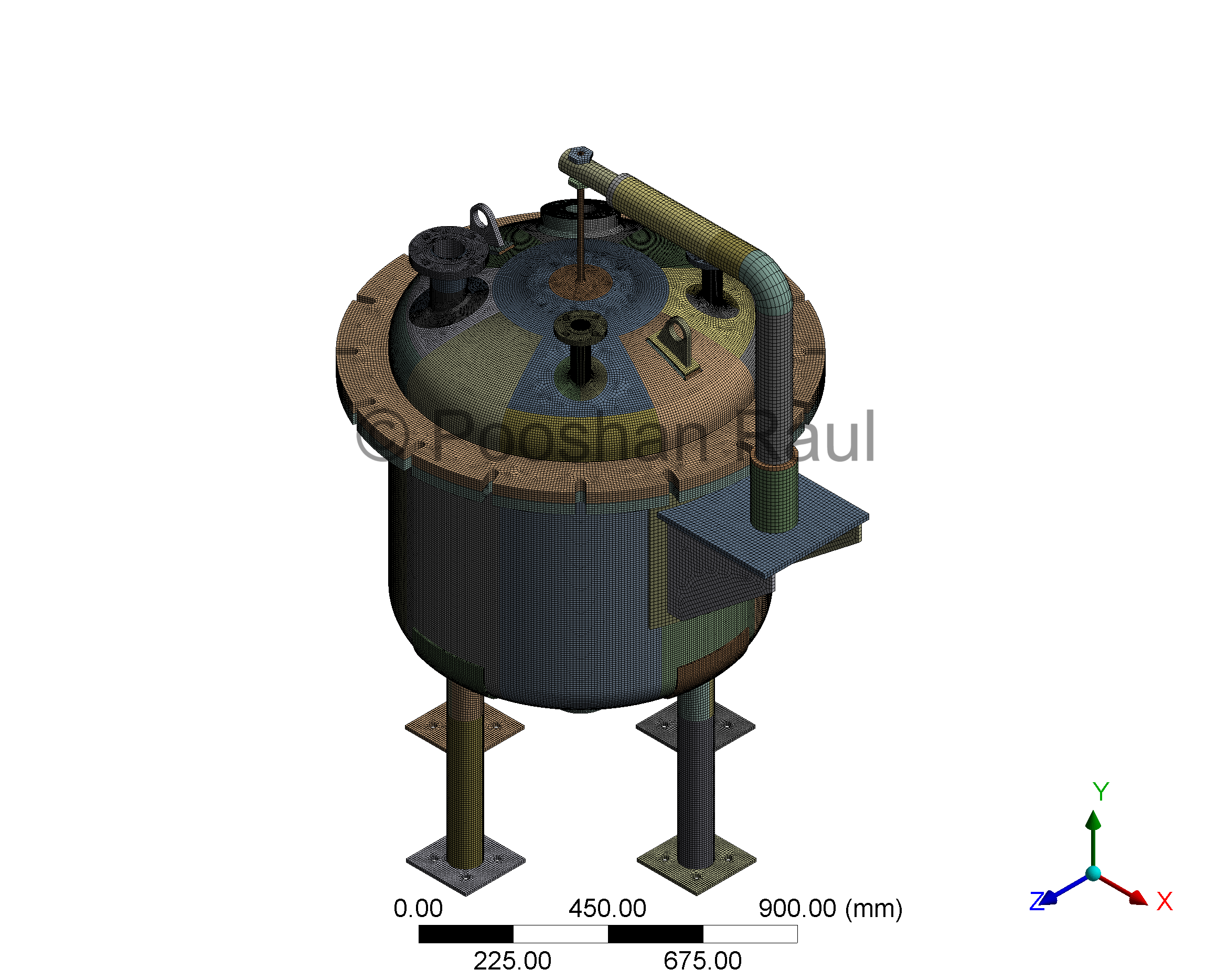
A multizone sweep mesh was applied using high-order SOLID186 elements to capture thermal and pressure-induced stress gradients. Local sizing controls ensured at least two elements through shell thickness in nozzle junctions and knuckle regions. Quality metrics such as Jacobian ratio and orthogonality were verified for solution accuracy.
- Element Type: SOLID186 (Quadratic, 20-node)
- Control: Local edge sizing & method controls
- Validation: Skewness, aspect ratio, warping factor, and Jacobian
Loading & Boundary Conditions
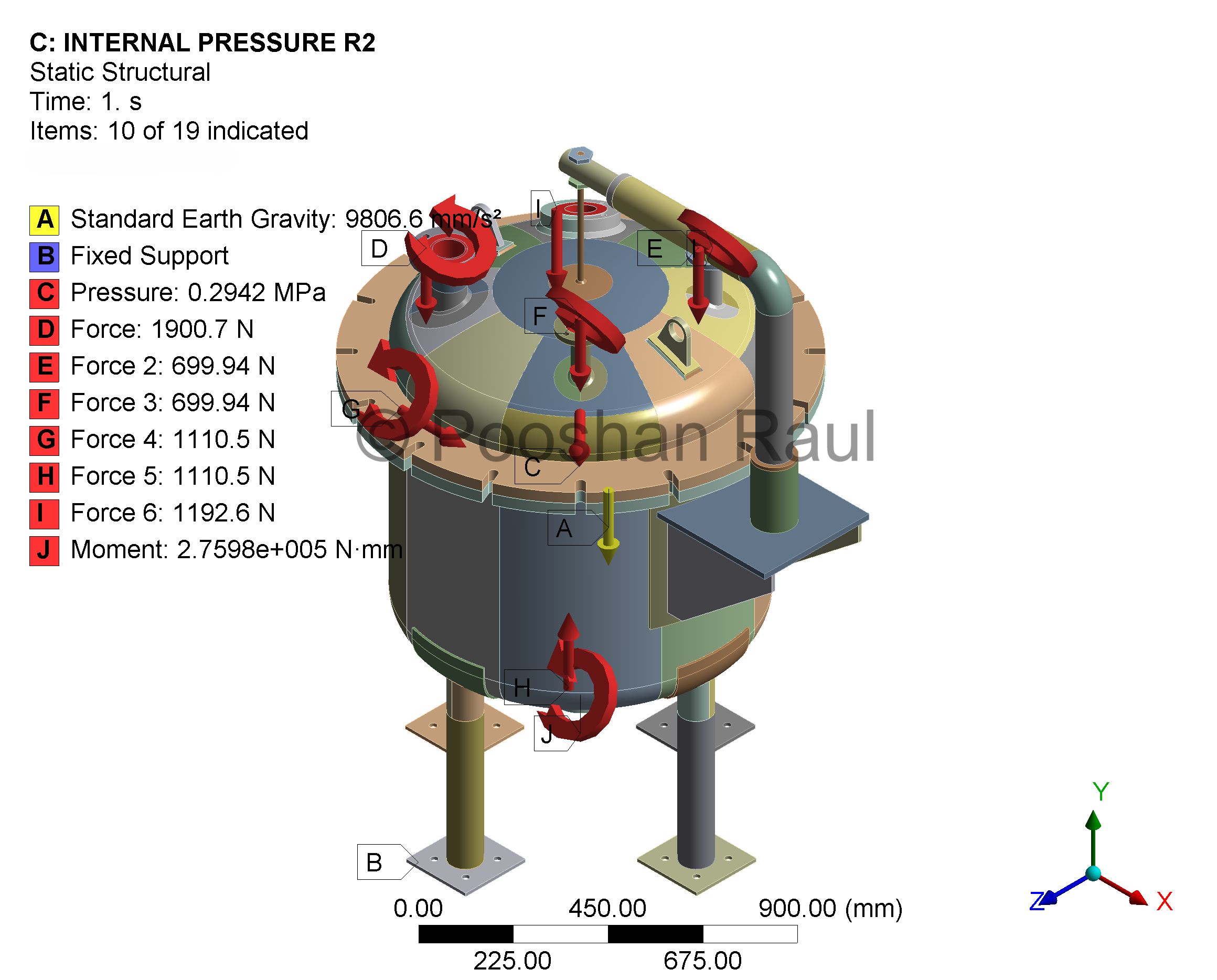
The vessel was subjected to 0.2942 MPa internal pressure, nozzle thrusts, and self-weight, with boundary conditions derived from WRC 2002 guidelines. Nozzle ends were constrained using realistic moment-bearing supports to simulate service-level stress paths at intersections.
- Supports: Fixed base
- Loads: Internal pressure, nozzle thrusts, gravity
- Nozzle Moments: Applied on cylindrical and torispherical zones
Stress Results
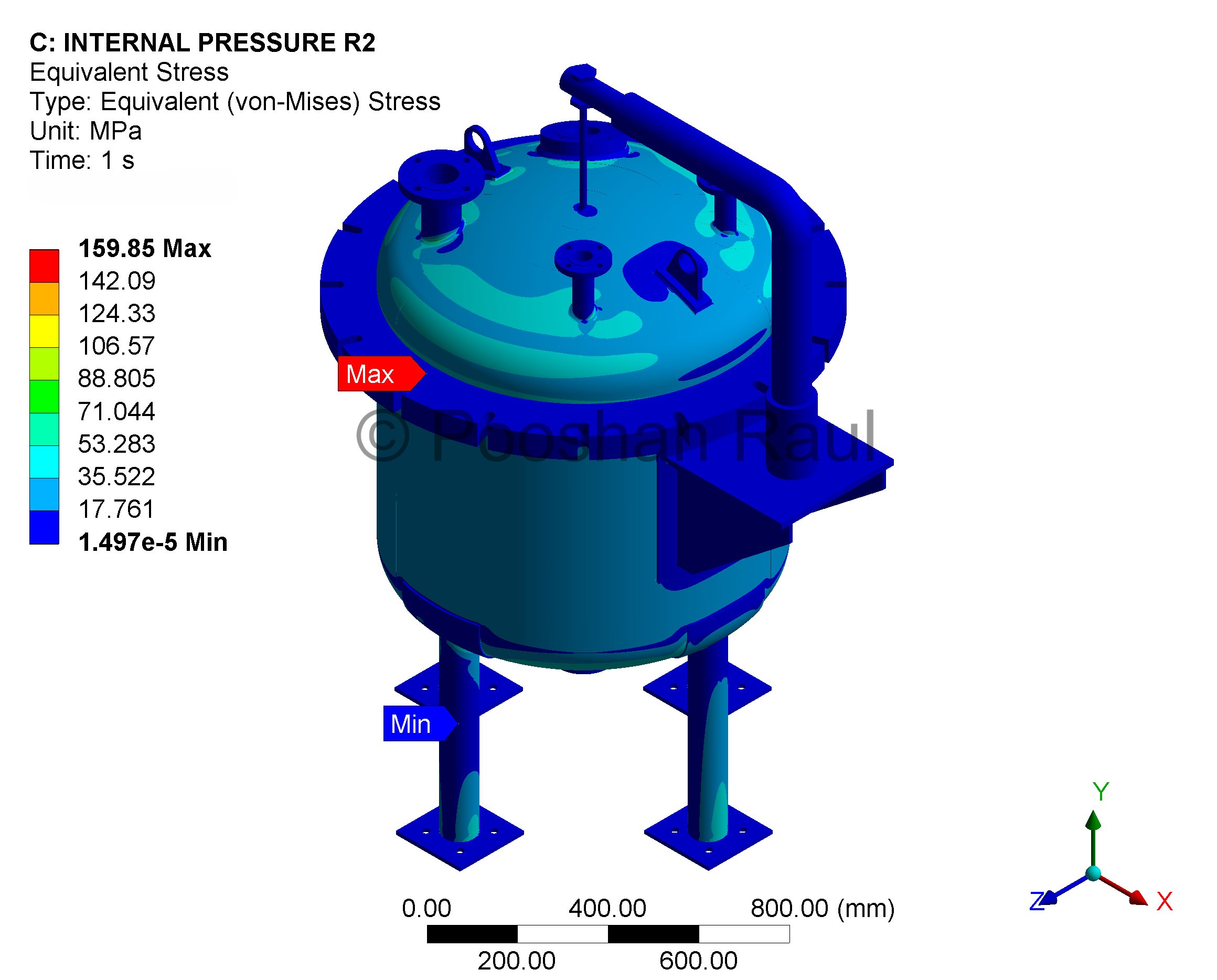
Von Mises stress concentration was observed at the nozzle-shell interface and around leg supports. All computed stress values remained within ASME allowable limits for SA-516 Gr.70 material, confirming pressure containment capacity with margin.
- Max Stress: 159.85 MPa
- Material Allowable stress: 235.5 MPa (1.5 × Sm)
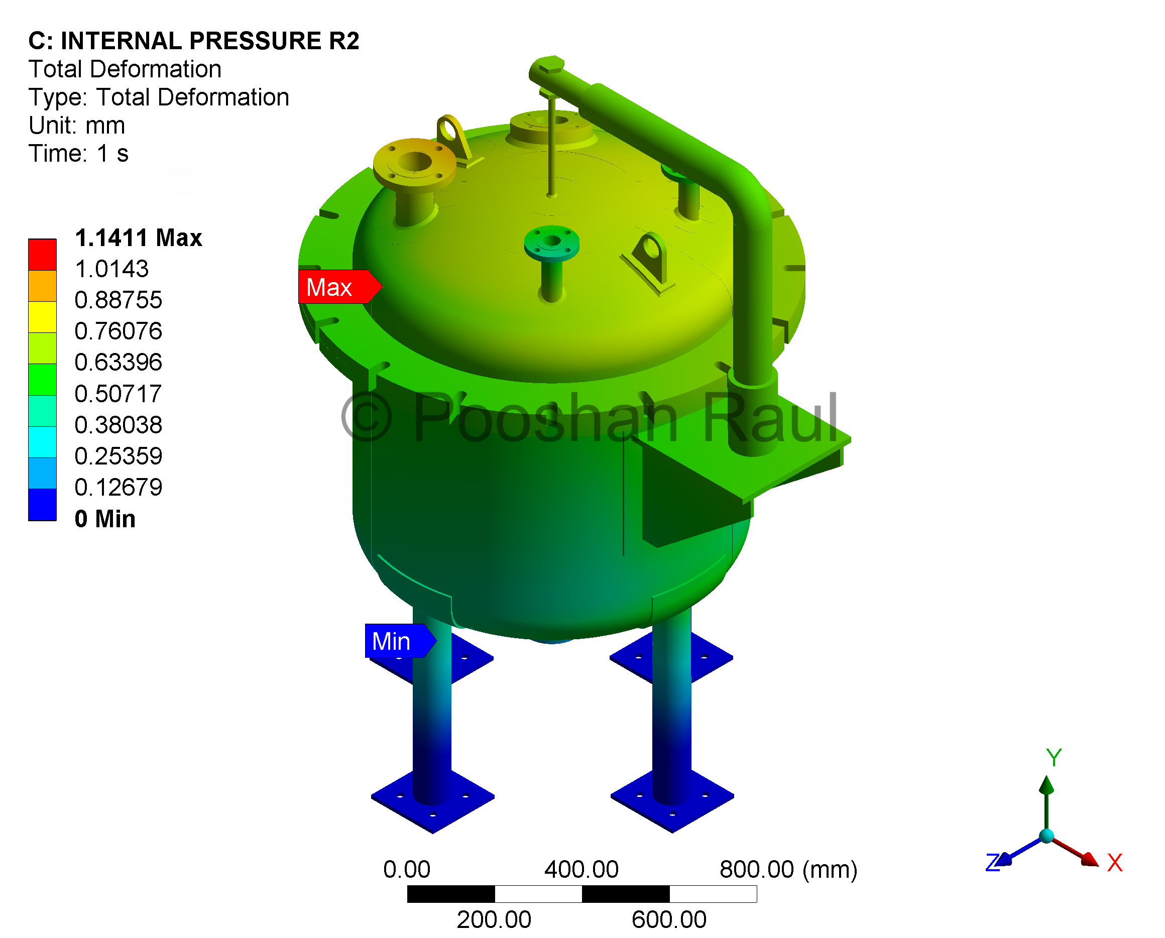
Total Deformation
Deformation was concentrated at unsupported shell nozzle. The peak deflection of 1.14 mm occurred within the elastic limit, demonstrating structural rigidity and service acceptability under combined loads. For additional safety, support strips were welded to the nozzle during manufacturing.
- Peak Deflection: 1.14 mm
- Location: At nozzle neck edges
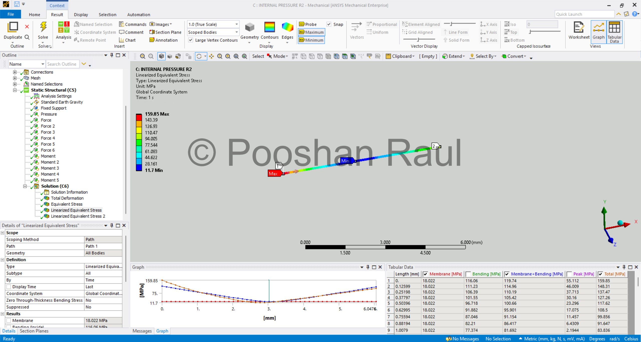 Stress linearisation result with tabular breakdown across shell thickness.
Stress linearisation
A linearized stress profile was extracted along a classification line plotted across shell and nozzle thickness at the nozzle interface, isolating membrane and bending components per ASME BPVC Section VIII, Div. 2 Chapter 5. The peak linearized stress (Pl + Pb) was significantly below the code-defined allowable threshold, passing compliance with margin.
- Max Linearized Stress (Pl + Pb): 119.74 MPa
- Allowable: 1.5 × Sm = 235.5 MPa
- Result: ✔ Pass
Project Summary & Analysis Workflow
This project demonstrates a full FEA validation workflow for a code-compliant pressure vessel design. Loads included internal pressure, thermal expansion, and nozzle thrusts. Service behavior was verified using WRC-based assumptions and membrane-bending stress separation. Simulation integrity was maintained via mesh convergence and Appendix 5 stress classification.
External nozzle loadings were interpreted using a WRC bulletin (2002 edition), accounting for axial, bending, and torsional components. These inputs enabled a realistic simulation of service-level stress behavior at nozzle-shell junctions.
CAD Modeling in SolidWorks → Geometry Cleanup → Import to ANSYS Workbench → Mesh Refinement → Load Application → Stress linearisation → ASME Code Validation → Experimental Hydrotesting
Material Validation: Properties were selected from ASME Section II, Part D, with yield strength values at design temperature referenced from Table Y-1. Allowable stress limits were determined per Annex 3-A, ensuring conformance with plastic collapse criteria under Division 2 rules.
This approach confirmed structural feasibility and demonstrated proficiency in both pressure vessel design standards and simulation workflow.
Project Information
- Project Date: September 2021
- Software: SolidWorks, ANSYS Mechanical
- Category: Pressure Equipment Design
- Focus Areas: FEA, ASME Code Compliance, Stress linearisation, Advanced Meshing